DYXNYQD-19 dynamic assembly disassembly work experimental device
Release time:2024-05-25 14:30viewed:times
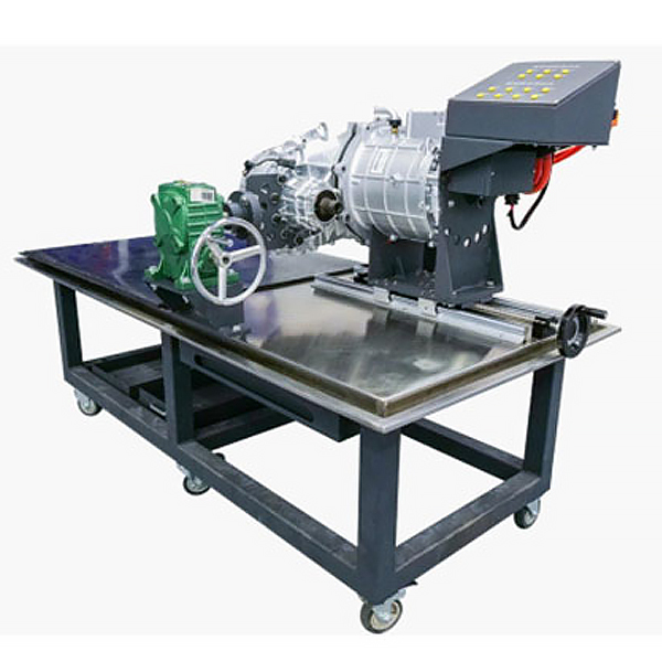
1. Product introduction: The electric drive assembly disassembly and assembly work platform is based on BYD power assembly and is equipped with a special flip frame connection mechanism to facilitate BYD power assembly disassembly, inspection and m*ntenance assessment. It is equipped with 360° arbitrary angle rotation and fixed flip. The frame can analyze and detect the wear of the m*n and countershaft gear sets of the powertr*n, measure and adjust data on the height and depth of the countershaft and differential, and select the adjustment pads for the countershaft and differential. Calculation exercises etc.
2. Technical requirements
(1) The desktop load-bearing panel is made of 10cm thick wooden boards, and the panel is equipped with high-quality st*nless steel bent panels. It is made of st*nless steel and is corrosion-resistant, easy to clean, evenly stressed and has strong load-bearing capacity.
(2) The platform is designed with a screw mechanism that separates the motor and gearbox and a 360° arbitrary flipping structure of the gearbox, making it easy and quick to disassemble and assemble the powertr*n. The separation of the motor and transmission does not require manual operation, effectively preventing accidents during tr*nee tr*ning.
(3) An oil tank is designed around the platform table. When the gear is disassembled, cleaned, and installed, the oil dirt can directly flow back to the oil collection device to keep the environment clean.
(4) The platform is supported by upper and lower double-layer structural beams, and the load-bearing beams are made of 80*40 U-shaped profiles, which is safe and stable.
(5) The platform is made of steel and can withstand a payload of no less than 1 ton.
(6) The platform effectively solves the high-frequency skill tr*ning for students in the disassembly, assembly and debugging of powertr*ns.
(7) The platform is equipped with a sheet metal set of disassembly parts such as gearbox gears, bearings, oil seals, circlips, etc. to avoid loss or wear caused by random placement of disassembly parts.
(8) The electric drive assembly includes the motor assembly, transmission, motor controller, related sensors , input and output interfaces, etc., and has the function of disassembly and debugging;
(9) It includes the hydraulic press, bearing disassembly and inspection tooling, and resolver inspection tooling. w*t.
1) The resolver detection tooling can provide excitation current for the resolver sensor;
2) The motor rotor can be rotated using special tools;
3) The dynamic waveform detection of the resolver signal can be carried out;
10) Mechanical assembly and fitter assembly virtual simulation software: this software Developed based on unity3d, with optional 6-level image quality, equipped with design and virtual disassembly and assembly of reducers and shafting structures, design and simulation of common mechanical mechanisms, mechanism resource library, typical mechanical mechanisms (virtual disassembly and assembly of gasoline engines), software It is a whole software, not individual resources.
A. Reducer design and virtual disassembly interface can choose worm gear bevel gear reducer, two-stage expanded cylindrical gear reducer, bevel cylindrical gear reducer, coaxial cylindrical gear reducer, bevel gear reducer, and one-stage cylindrical gear reducer. Gear reducer.
Worm bevel gear reducer: After entering the software, the assembly content is automatically played. Each step in the video has a text description
. Secondary expandable cylindrical gear reducer: After entering the software, the content is played in the form of a video. The video content should include: Part name ( Scan the QR code to see the names of parts), disassembly and assembly demonstration (including disassembly and assembly), virtual disassembly (including overall, low-speed shaft, medium-speed shaft, high-speed shaft, box cover, box seat)
conical cylindrical gear reducer, Coaxial cylindrical gear reducer, bevel gear reducer, first-level cylindrical gear reducer: click to enter and automatically jump to the edrawings interface. The models are all three-dimensional models . By clicking on the parts, the names of the parts are displayed, and the 360° view is av*lable Rotate, enlarge, reduce, translate, and at the same time, the entire reducer can be disassembled and assembled through the moving parts function. At the same time, you can select the home button to return to the original state of the reducer. The bevel gear reducer and first-stage cylindrical gear reducer have added the function of inserting a cross section, and the cross section can be freely dragged to observe the internal structure of the reducer.
B. Shaft structure design and virtual disassembly and assembly interface optional parts recognition, disassembly and assembly demonstration, and actual operation.
1. Parts recognition: three-dimensional model and part name including helical gear, non-hole end cover, coupling, coupling key, shaft, gear key, hole end cover, shaft sleeve, deep groove ball bearing, any All parts can be rotated 360°
2. Disassembly and assembly demonstration: There are 2 built-in cases. When you move the mouse to the position of a cert*n part (except the base and bearing seat), the part will automatically enlarge and the name of the part will be displayed. It is equipped with disassembly and Assembly button, the function is to automatically complete the disassembly and assembly of the shaft system structure by the software. All three-dimensional scenes can be rotated, enlarged, reduced and translated 360° in all directions.
3. Practical operation: The three-dimensional parts are neatly placed on the table. Students manually select the corresponding parts and move them to the shaft system structure. The parts can be installed only when they are placed in the correct order and in the correct position. There is a restart button to facilitate students to restart. Conduct virtual experiments. When you move the mouse to a cert*n part position (except the base and bearing seat), the part will automatically enlarge and the part name will be displayed.
C. Common mechanical mechanism design and simulation, optional hinge four-bar mechanism design and analysis, I\II type crank rocker mechanism design and analysis, offset crank slider mechanism design and analysis, crank swing guide rod mechanism design and analysis, hinge Four-bar mechanism with integrated trajectory, eccentric linear-acting roller push rod cam , and centering linear-acting flat-bottomed push rod cam .
1. Each mechanism should be able to input corresponding parameters, and the software can automatically calculate the parameters, and can perform motion simulation and automatically draw curves.
D. The mechanism resource library includes 11 types of planar link mechanisms, 5 types of cam mechanisms, 6 types of gear mechanisms, 8 types of transmission mechanisms, 11 types of tightening mechanisms, 6 types of gear tr*n mechanisms, and 8 types of other mechanisms (mechanical equipment simulation)
E , virtual disassembly and assembly of gasoline engines, optional crankcase assembly and disassembly demonstration, crankcase virtual assembly, valve tr*n assembly and disassembly demonstration, valve tr*n virtual assembly
1, crankcase assembly and disassembly demonstration and valve tr*n assembly and disassembly demonstration both have disassembly button, assembly button, restart, and decomposition observation button. When the mouse is moved to a cert*n part position, the part will automatically enlarge and the part name will be displayed. The software automatically completes the disassembly and assembly of the shaft system structure. When using the decomposition observation button, the 3D model of the crankcase or gas distribution system automatically displays an exploded view, which can be rotated, enlarged, reduced and translated 360° in all directions.
2. The three-dimensional parts of the crankcase virtual assembly and the gas distribution system virtual assembly are neatly placed on the desktop. Students manually select the corresponding parts and move them to the mechanism. The parts can be installed only when they are placed in the correct order and in the correct position. There is a restart button to facilitate students to re-run virtual experiments. When you move the mouse to cert*n part locations, the part names are automatically displayed.
3. Technical parameters Motor parameters meet:
Maximum output torque: ≥310N.m
Rated torque: ≥160N.m
Maximum input power: ≥160kW
Rated power: ≥80kW
Maximum output speed: ≥12000rpm


 Wechat scan code follow us
