dyxnydc-07 power conversion technology experimental device
Release time:2024-05-25 02:30viewed:times
1. Product Introduction
Using the new energy vehicle power conversion system module, you can connect DC-AC, AC-DC, boost, buck and other circuits to demonstrate the structure and control principle of the power conversion system. Suitable for understanding and verifying DC-AC, AC-DC, step-up and step-down teaching and tr*ning experiments.
2. Functional features
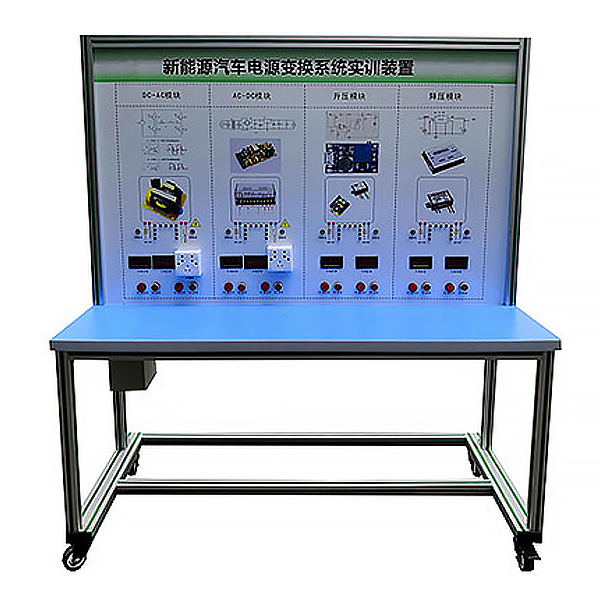
1. This equipment completely displays the new energy vehicle power conversion system, and can be connected to DC-AC, AC-DC, boost, buck and other circuits to display the structure and control logic of each system.
2. The panel is made of 4mm thick aluminum-plastic plate, and the panel is printed with color circuit diagrams and working principle schematics that will never fade; students can visually compare the schematic diagram with the actual object to understand and analyze the working principle of the system.
3. The panel is equipped with ignition switch, DC-AC, AC-DC, boost and step-down modules, etc., supplemented by light-emitting diodes for dynamic indication of system flow direction, and analog indicators to demonstrate the work of power conversion. Status, key component position setting detection terminals, instruments can be used to measure parameters.
6. The equipment frame is constructed of two integrated all-aluminum alloy profiles, 40mm×40mm and 40mm×80mm, which are oil-resistant, corrosion-resistant and easy to clean. The countertop is 40CM wide and paved with 32mm thick colored high-density composite boards, which is durable and rust-free. , with 4 swivel casters with self-locking devices for easy movement.
7. It is equipped with teaching materials such as practical tr*ning instructions, which fully describe the working principles, practical tr*ning projects, etc.
8. Mechanical assembly and fitter assembly virtual simulation software: This software is developed based on unity3d, with optional 6-level image quality. It is equipped with the design and virtual disassembly and assembly of reducers and shafting structures, the design and simulation of common mechanical mechanisms , and a mechanism resource library. For a typical mechanical mechanism (virtual disassembly and assembly of a gasoline engine), the software is a whole software and cannot be individual resources.
A. Reducer design and virtual disassembly interface can choose worm gear bevel gear reducer, two-stage expanded cylindrical gear reducer, bevel cylindrical gear reducer, coaxial cylindrical gear reducer, bevel gear reducer, and one-stage cylindrical gear reducer. Gear reducer.
Worm bevel gear reducer: After entering the software, the assembly content is automatically played. Each step in the video has a text description
. Secondary expandable cylindrical gear reducer: After entering the software, the content is played in the form of a video. The video content should include: Part name ( Scan the QR code to see the names of parts), disassembly and assembly demonstration (including disassembly and assembly), virtual disassembly (including overall, low-speed shaft, medium-speed shaft, high-speed shaft, box cover, box seat)
conical cylindrical gear reducer, Coaxial cylindrical gear reducer, bevel gear reducer, first-level cylindrical gear reducer: click to enter and automatically jump to the edrawings interface. The models are all three-dimensional models . By clicking on the parts, the names of the parts are displayed, and the 360° view is av*lable Rotate, enlarge, reduce, translate, and at the same time, the entire reducer can be disassembled and assembled through the moving parts function. At the same time, you can select the home button to return to the original state of the reducer. The bevel gear reducer and first-stage cylindrical gear reducer have added the function of inserting a cross section, and the cross section can be freely dragged to observe the internal structure of the reducer.
B. Shaft structure design and virtual disassembly and assembly interface optional parts recognition, disassembly and assembly demonstration, and actual operation.
1. Parts recognition: three-dimensional model and part name including helical gear, non-hole end cover, coupling, coupling key, shaft, gear key, hole end cover, shaft sleeve, deep groove ball bearing, any All parts can be rotated 360°
2. Disassembly and assembly demonstration: There are 2 built-in cases. When you move the mouse to the position of a cert*n part (except the base and bearing seat), the part will automatically enlarge and the name of the part will be displayed. It is equipped with disassembly and Assembly button, the function is to automatically complete the disassembly and assembly of the shaft system structure by the software. All three-dimensional scenes can be rotated, enlarged, reduced and translated 360° in all directions.
3. Practical operation: The three-dimensional parts are neatly placed on the table. Students manually select the corresponding parts and move them to the shaft system structure. The parts can be installed only when they are placed in the correct order and in the correct position. There is a restart button to facilitate students to restart. Conduct virtual experiments. When you move the mouse to a cert*n part position (except the base and bearing seat), the part will automatically enlarge and the part name will be displayed.
C. Common mechanical mechanism design and simulation, optional hinge four-bar mechanism design and analysis, I\II type crank rocker mechanism design and analysis, offset crank slider mechanism design and analysis, crank swing guide rod mechanism design and analysis, hinge Four-bar mechanism with integrated trajectory, eccentric linear-acting roller push rod cam , and centering linear-acting flat-bottomed push rod cam .
1. Each mechanism should be able to input corresponding parameters, and the software can automatically calculate the parameters, and can perform motion simulation and automatically draw curves.
D. The mechanism resource library includes 11 types of planar link mechanisms, 5 types of cam mechanisms, 6 types of gear mechanisms, 8 types of transmission mechanisms, 11 types of tightening mechanisms, 6 types of gear tr*n mechanisms, and 8 types of other mechanisms (mechanical equipment simulation)
E , virtual disassembly and assembly of gasoline engines, optional crankcase assembly and disassembly demonstration, crankcase virtual assembly, valve tr*n assembly and disassembly demonstration, valve tr*n virtual assembly
1, crankcase assembly and disassembly demonstration and valve tr*n assembly and disassembly demonstration both have disassembly button, assembly button, restart, and decomposition observation button. When the mouse is moved to a cert*n part position, the part will automatically enlarge and the part name will be displayed. The software automatically completes the disassembly and assembly of the shaft system structure. When the decomposition observation button is used, the 3D model of the crankcase or gas distribution system automatically displays an exploded view, which can be rotated, enlarged, reduced, and translated 360°.
2. The 3D parts of the crankcase virtual assembly and the gas distribution system virtual assembly are neatly arranged When placed on the desktop, students manually select the corresponding parts and move them to the mechanism. The parts can be installed only when they are placed in the correct order and in the correct position. There is a restart button to facilitate students to re-perform the virtual experiment. When you move the mouse to cert*n part locations, the part names are automatically displayed.
3. Technical specifications
1. External power supply: AC 220V±10% 50Hz
2. Working voltage: AC 220V, etc.
3. Working temperature: -40℃~+50℃
4. Overall dimensions: 1500×700×1700mm (length×width× high)
5. Power conversion module: DC-AC module (12V to 220V), AC-DC module (220V to 12V), boost module (12V to 24V), step-down module (24V to 12V).
4. Practical tr*ning experiment project
1. Functional understanding of DC-DC converter for new energy vehicles.
2. Understanding the structural principles of DC-DC converters for new energy vehicles.
3. Functional understanding of DC-AC converters for new energy vehicles.
4. Understanding of the structural principles of DC-AC converters for new energy vehicles.
5. Functional understanding of AC-DC converters for new energy vehicles.
6. Understanding the structural principles of AC-DC converters for new energy vehicles.
five. Basic configuration (per unit)
DC-AC module (12V to 220V), ignition switch, AC-DC module (220V to 12V), boost module (12V to 24V), buck module (24V to 12V), LED flash Light bar, indicator light, operating switch, contactor, emergency stop switch, integrated all-aluminum alloy profile mobile stand (1500×700×1700mm with self-locking caster device, principle panel with installation detection terminals, panel 1448× 940mm), equipment operating instructions.


 Wechat scan code follow us
