DYXNYDC-04 power battery installation and test smart teaching experimental device
Release time:2024-05-24 22:00viewed:times
1. The m*n functions
meet the battery assembly and debugging capabilities, including the assembly and debugging of power batteries, the assembly and measurement of single cells, the assembly and measurement of battery modules, the assembly and measurement of DC charging interfaces, and the assembly and measurement of AC charging interfaces. Measurement. Meet the following practical tr*ning items: Cell voltage test. Cell internal resistance test. Single battery classification. Module disassembly, coding, debugging and testing. Disassembly, debugging and testing of power batteries. Contactor disassembly and measurement. Disassembly and assembly of AC and DC charging interfaces. Disassembly and assembly of manual service switch. Disassembly, assembly and measurement of current sensors . Precharge resistor disassembly, assembly and measurement. Disassembly and assembly of high-voltage connectors. Air tightness testing of thermal management systems. PACK *r tightness testing. BMS installation. Charge and discharge test. DC charging interface assembly and charging debugging. Disassembly and assembly of high and low voltage wiring harnesses. Disassembly and assembly of other accessories. It can be tested in conjunction with the AC charging pile installation and adjustment station and the drive motor installation and adjustment station for mutual verification.
2. M*n technical requirements
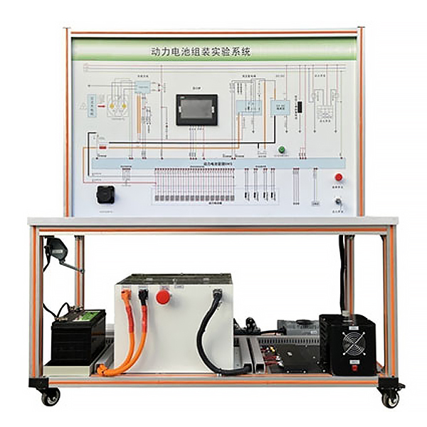
(1) Power battery assembly and adjustment station metal body, overall size of the equipment (length*width*height): about 1630*780*1730mm
(2) Power battery
①Battery management system (BMS) working voltage range: DC 9~36V. Working temperature range: -40℃~85℃. Storage temperature range: -40℃~125℃. Working humidity range (%): 0~95%. Single cell voltage detection range: 0~5V. Single battery voltage sampling accuracy: ≤5mV. Single battery voltage sampling frequency: ≤100ms. Total voltage detection accuracy: <1%. Temperature measurement range: -40~125℃. Temperature detection accuracy: ±1℃. Current detection range: ≤75A.
②Car charger. Altitude: ≤3000m full load output. Storage environment temperature: -40℃~80℃. Working environment temperature: -20℃~55℃ normal operation; 55℃~75℃ derated output. Relative humidity: 0~95%. Installation environment: no severe vibration and impact. Dust environment: no conductive or explosive dust, no gas or vapor that corrodes metal and damages insulation. Specifications and models: 75V 10A. Input voltage: ≥220V AC. Working frequency: 50/60Hz. CC, CP functions: Yes. Output voltage: ≥75V DC. Output current: ≤10A. Output power: ≥800W. Voltage stabilization accuracy: ≤1%. Steady flow accuracy: ≤1%. Voltage ripple (PP): ≤1%. Work efficiency: ≥0.93. Input over-voltage protection value: protective shutdown when higher than 260V AC
Input under-voltage protection value: no startup when below 176V AC. Over-temperature protection value: shuts down when the temperature is higher than 80℃, and can recover automatically when it is lower than 60℃. Output overvoltage protection: ≥80V DC. Output overcurrent protection ≥12A. Output under-voltage protection: The battery pack will not start if the voltage is lower than 10V. Output short circuit protection: constant current after short circuit, self-recovery after release. Output reverse connection protection: it will not start after reverse connection, and will recover automatically after being released. Insulation resistance input to output DC1000V≥100MΩ. Input to chassis: DC1000V≥100MΩ. Output to chassis: DC1000V≥100MΩ. Communication: CAN 2.0. Auxiliary power supply: ≤12V 3A. Cooling method: *r cooling. Protection level: IP65. Connector: aviation plug. Working noise: ≤60dB.
③Single battery. Voltage: 3.2V. Capacity: 30AH. Type: Lithium Iron Phosphate.
④Temperature sensor. Normal temperature resistance value: 1000Ω. Working temperature range: -40℃~85℃. Storage temperature range: -40℃~125℃. Working humidity range (%): 0~95%. Temperature detection accuracy: ±1℃. Terminal form: screw terminal block.
⑤High voltage relay. Contact rated current: 0~500A. Coil voltage: 9~36V. Maximum rated working voltage: 0~2200V. Terminal form: Bolt terminal block
⑥ Precharge resistor. Resistor value: 100Ω. Resistor power: 100W. Resistor Category: Wirewound Resistors. Packaging material: industrial aluminum. Lead wiring: Teflon high temperature wire.
(3) All-in-one teaching machine. System: Windows. Display specifications: 55 inches. Memory: 8G+512G. Processor: i5. Whether the screen is touchable: touch control.
(4) Insulation tool set. Tool material: alloy tool steel. Withstand voltage: 1KV. Format: Metric
(5) Test instrument ① Battery internal resistance voltmeter test method; AC four-terminal test. Resistance resolution: 0.1mΩ. Voltage measurement accuracy; 100mV. Voltage measurement range; 0-100V. Internal resistance measurement range; 1mΩ-199.9 mΩ. ②Insulation resistance tester. Insulation resistance measurement: 4000MΩ. Voltage measurement: DC voltage: DC0V-±1000V. AC voltage: AC30V-750V. Short circuit current: about 1.3mA. ③Ground resistance tester. Ground resistance measurement range: 0-2000Ω. Ground voltage measurement range: 0-200V③Digital multimeter. DC voltage: 400mV-1000V. AC voltage: 400mV-750V. DC current: 400μA-10A. AC current: 400μA-10A. Resistance: 400Ω-40MΩ Capacitance: 4nF-40mF Frequency: 9.999Hz-9.999MHz Transistor hFE test: 1-1000 Temperature: -40℃-1000℃ Diode and continuity test
mechanical assembly and fitter assembly virtual simulation software: This software is based on unity3d Development, optional 6-level image quality, equipped with design and virtual disassembly and assembly of reducers and shafting structures, design and simulation of common mechanical mechanisms , mechanism resource library, typical mechanical mechanisms (virtual disassembly and assembly of gasoline engines), the software is a The overall software cannot be individual resources.
A. Reducer design and virtual disassembly interface can choose worm gear bevel gear reducer, two-stage expanded cylindrical gear reducer, bevel cylindrical gear reducer, coaxial cylindrical gear reducer, bevel gear reducer, and one-stage cylindrical gear reducer. Gear reducer.
Worm bevel gear reducer: After entering the software, the assembly content is automatically played. Each step in the video has a text description
. Secondary expandable cylindrical gear reducer: After entering the software, the content is played in the form of a video. The video content should include: Part name ( Scan the QR code to see the names of parts), disassembly and assembly demonstration (including disassembly and assembly), virtual disassembly (including overall, low-speed shaft, medium-speed shaft, high-speed shaft, box cover, box seat)
conical cylindrical gear reducer, Coaxial cylindrical gear reducer, bevel gear reducer, first-level cylindrical gear reducer: click to enter and automatically jump to the edrawings interface. The models are all three-dimensional models., by clicking on the component to display the component name, you can rotate, enlarge, reduce and pan 360°. At the same time, you can disassemble and assemble the entire reducer through the move component function. At the same time, you can select the home button to return to the reducer** *Initial state. The bevel gear reducer and first-stage cylindrical gear reducer have added the function of inserting a cross section, and the cross section can be freely dragged to observe the internal structure of the reducer.
B. Shaft structure design and virtual disassembly and assembly interface optional parts recognition, disassembly and assembly demonstration, and actual operation.
1. Parts recognition: three-dimensional model and part name including helical gear, non-hole end cover, coupling, coupling key, shaft, gear key, hole end cover, shaft sleeve, deep groove ball bearing, any All parts can be rotated 360°
2. Disassembly and assembly demonstration: There are 2 built-in cases. When you move the mouse to the position of a cert*n part (except the base and bearing seat), the part will automatically enlarge and the name of the part will be displayed. It is equipped with disassembly and Assembly button, the function is to automatically complete the disassembly and assembly of the shaft system structure by the software. All three-dimensional scenes can be rotated, enlarged, reduced and translated 360° in all directions.
3. Practical operation: The three-dimensional parts are neatly placed on the table. Students manually select the corresponding parts and move them to the shaft system structure. The parts can be installed only when they are placed in the correct order and in the correct position. There is a restart button to facilitate students to restart. Conduct virtual experiments. When you move the mouse to a cert*n part position (except the base and bearing seat), the part will automatically enlarge and the part name will be displayed.
C. Common mechanical mechanism design and simulation, optional hinge four-bar mechanism design and analysis, I\II type crank rocker mechanism design and analysis, offset crank slider mechanism design and analysis, crank swing guide rod mechanism design and analysis, hinge Four-bar mechanism with integrated trajectory, eccentric linear-acting roller push rod cam , and centering linear-acting flat-bottomed push rod cam .
1. Each mechanism should be able to input corresponding parameters, and the software can automatically calculate the parameters, and can perform motion simulation and automatically draw curves.
D. The mechanism resource library includes 11 types of planar link mechanisms, 5 types of cam mechanisms, 6 types of gear mechanisms, 8 types of transmission mechanisms, 11 types of tightening mechanisms, 6 types of gear tr*n mechanisms, and 8 types of other mechanisms (mechanical equipment simulation)
E , virtual disassembly and assembly of gasoline engines, optional crankcase assembly and disassembly demonstration, crankcase virtual assembly, valve tr*n assembly and disassembly demonstration, valve tr*n virtual assembly
1, crankcase assembly and disassembly demonstration and valve tr*n assembly and disassembly demonstration both have disassembly button, assembly button, restart, and decomposition observation button. When the mouse is moved to a cert*n part position, the part will automatically enlarge and the part name will be displayed. The software automatically completes the disassembly and assembly of the shaft system structure. When the decomposition observation button is used, the 3D model of the crankcase or gas distribution system automatically displays an exploded view, which can be rotated, enlarged, reduced, and translated 360°.
2. The 3D parts of the crankcase virtual assembly and the gas distribution system virtual assembly are neatly arranged When placed on the desktop, students manually select the corresponding parts and move them to the mechanism. The parts can be installed only when they are placed in the correct order and in the correct position. There is a restart button to facilitate students to re-perform the virtual experiment. When you move the mouse to cert*n part locations, the part names are automatically displayed.
Battery management system host computer system (used in conjunction with the CAN box)
Battery management system connection method: CAN-H, CAN-L two-wire harness connection.
Safety warning: Displays the fault information detected by the current system. When the system parameters meet the preset values, it will display no fault; when a fault is detected, the cause of the fault will be displayed; if more than one fault occurs, the user can directly Click here to view all breakdowns.
The host computer system constantly monitors and displays the total voltage of the power battery assembly, the highest battery temperature, the lowest battery temperature, temperature difference, SOC value, the highest voltage of the single unit, the lowest voltage of the single unit, and the pressure difference.
Click "Real-time Information" on the m*n interface to view the voltage value of each cell in the current battery pack and the temperature information of each box.
After the connection is started, the host machine receives the information from the BMS and displays it in real time. (If the connection f*lure is displayed, please reinstall the CAN box driver and connect ag*n.) The information on the m*n page m*nly includes the following information:
Enter configuration-select the cell voltage fault parameter reading: After clicking Read parameters, you can read the cell Overvoltage first-level fault threshold, single overvoltage first-level fault release threshold, single overvoltage second-level fault threshold, single overvoltage second-level fault release threshold, single overvoltage third-level fault threshold, Single unit overvoltage level 3 fault release threshold, unit undervoltage level 1 fault release threshold, unit undervoltage level 1 fault release threshold, unit undervoltage level 2 fault release threshold, unit undervoltage level 2 fault release Parameter information of threshold, unit undervoltage level 3 fault threshold, unit undervoltage level 3 fault release threshold.
Enter the configuration-select the temperature fault parameters: high temperature first-level fault threshold, high temperature first-level fault release threshold, high temperature second-level fault threshold, high temperature second-level fault release threshold, high temperature third-level fault threshold, high temperature third-level fault release Parameter information of threshold, low temperature first-level fault threshold, low temperature first-level fault release threshold, low temperature second-level fault threshold, low temperature second-level fault release threshold, low temperature third-level fault threshold, low temperature third-level fault release threshold .
Enter the insulation detection-to read information about the status of the insulation detector, insulation resistance, and battery voltage.


 Wechat scan code follow us
