DyxnyDQ-01 New Energy Vehicle Electronic and Car CAN CAN Network System Experimental Device
Release time:2024-05-24 08:30viewed:times
1. Functional features
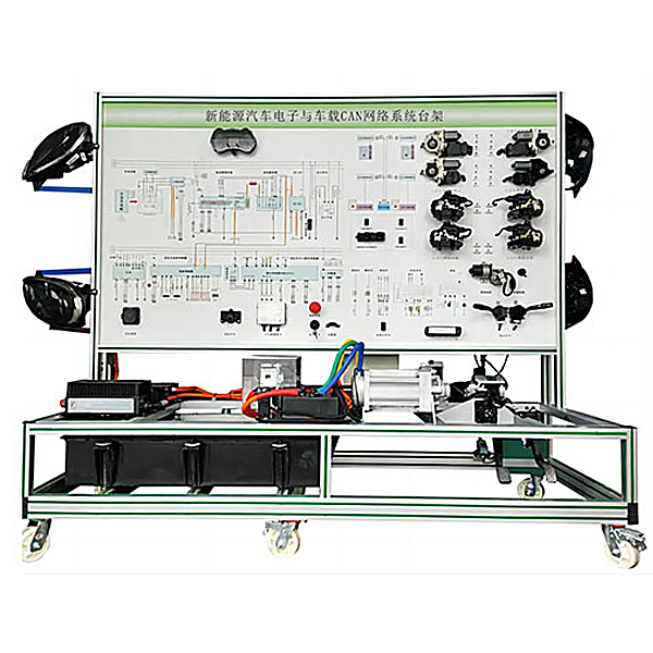
1. This device completely displays the CAN bus network system of the electric vehicle (including VCU system/ motor control/battery management system/charging system), and can dynamically simulate the operating status and working process of the vehicle CAN bus network.
2. The panel is made of 4mm thick high-grade aluminum-plastic panels that are corrosion-resistant, impact-resistant, pollution-resistant, fire-proof, and moisture-proof. The surface is sprayed with primer using a special process; the panel is printed with color circuit diagrams and working principle schematics that will never fade; students can Intuitively compare the structural schematic diagram and actual objects of the CAN bus network system of the electric vehicle to understand and analyze the working principle of the CAN bus network system of the electric vehicle.
3. Install ignition switch, vehicle controller module with gateway communication, intelligent instrument module, power system module, motor controller, working condition indicator light, power switch, accelerator pedal, brake pedal, power motor and other modules and controls switch.
4. The equipment frame is constructed of two integrated all-aluminum alloy profiles, 40mm×40mm and 40mm×80mm, which are oil-resistant, corrosion-resistant and easy to clean. The countertop is 40CM wide and paved with 32mm thick colored high-density composite boards, which is durable and rust-free. , with 4 swivel casters with self-locking devices for easy movement.
5. The installation of a fault simulation system can realize fault setting and diagnosis and elimination of low-voltage circuit systems. It can set up 24 common fault settings and assess fault points.
6. Mechanical assembly and fitter assembly virtual simulation software: This software is developed based on unity3d, with optional 6-level image quality. It is equipped with the design and virtual disassembly and assembly of reducers and shafting structures, the design and simulation of common mechanical mechanisms , and a mechanism resource library. For a typical mechanical mechanism (virtual disassembly and assembly of a gasoline engine), the software is a whole software and cannot be individual resources.
A. Reducer design and virtual disassembly interface can choose worm gear bevel gear reducer, two-stage expanded cylindrical gear reducer, bevel cylindrical gear reducer, coaxial cylindrical gear reducer, bevel gear reducer, and one-stage cylindrical gear reducer. Gear reducer.
Worm bevel gear reducer: After entering the software, the assembly content is automatically played. Each step in the video has a text description
. Secondary expandable cylindrical gear reducer: After entering the software, the content is played in the form of a video. The video content should include: Part name ( Scan the QR code to see the names of parts), disassembly and assembly demonstration (including disassembly and assembly), virtual disassembly (including overall, low-speed shaft, medium-speed shaft, high-speed shaft, box cover, box seat)
conical cylindrical gear reducer, Coaxial cylindrical gear reducer, bevel gear reducer, first-level cylindrical gear reducer: click to enter and automatically jump to the edrawings interface. The models are all three-dimensional models . By clicking on the parts, the names of the parts are displayed, and the 360° view is av*lable Rotate, enlarge, reduce, translate, and at the same time, the entire reducer can be disassembled and assembled through the moving parts function. At the same time, you can select the home button to return to the original state of the reducer. The bevel gear reducer and the first-stage cylindrical gear reducer have added the function of inserting a cross section, and the cross section can be freely dragged to observe the internal structure of the reducer.
B. Shaft structure design and virtual disassembly and assembly interface optional parts recognition, disassembly and assembly demonstration, and actual operation.
1. Parts recognition: three-dimensional model and part name including helical gear, non-hole end cover, coupling, coupling key, shaft, gear key, hole end cover, shaft sleeve, deep groove ball bearing, any All parts can be rotated 360°
2. Disassembly and assembly demonstration: There are 2 built-in cases. When you move the mouse to the position of a cert*n part (except the base and bearing seat), the part will automatically enlarge and the name of the part will be displayed. It is equipped with disassembly and Assembly button, the function is to automatically complete the disassembly and assembly of the shaft system structure by the software. All three-dimensional scenes can be rotated, enlarged, reduced and translated 360° in all directions.
3. Practical operation: The three-dimensional parts are neatly placed on the table. Students manually select the corresponding parts and move them to the shaft system structure. The parts can be installed only when they are placed in the correct order and in the correct position. There is a restart button to facilitate students to restart. Conduct virtual experiments. When you move the mouse to a cert*n part position (except the base and bearing seat), the part will automatically enlarge and the part name will be displayed.
C. Common mechanical mechanism design and simulation, optional hinge four-bar mechanism design and analysis, I\II type crank rocker mechanism design and analysis, offset crank slider mechanism design and analysis, crank swing guide rod mechanism design and analysis, hinge Four-bar mechanism with integrated trajectory, eccentric linear-acting roller push rod cam , and centering linear-acting flat-bottomed push rod cam .
1. Each mechanism should be able to input corresponding parameters, and the software can automatically calculate the parameters, and can perform motion simulation and automatically draw curves.
D. The mechanism resource library includes 11 types of planar link mechanisms, 5 types of cam mechanisms, 6 types of gear mechanisms, 8 types of transmission mechanisms, 11 types of tightening mechanisms, 6 types of gear tr*n mechanisms, and 8 types of other mechanisms (mechanical equipment simulation)
E , virtual disassembly and assembly of gasoline engines, optional crankcase assembly and disassembly demonstration, crankcase virtual assembly, valve tr*n assembly and disassembly demonstration, valve tr*n virtual assembly
1. Crankcase assembly and disassembly demonstration and valve tr*n assembly and disassembly demonstration both have disassembly button, assembly button, restart, and decomposition observation button. When the mouse is moved to a cert*n part position, the part will automatically enlarge and the part name will be displayed. The software automatically completes the disassembly and assembly of the shaft system structure. When using the decomposition observation button, the 3D model of the crankcase or gas distribution system automatically displays an exploded view, which can be rotated, enlarged, reduced, and translated 360°.
2. The 3D parts of the crankcase virtual assembly and the gas distribution system virtual assembly are neatly arranged When placed on the desktop, students manually select the corresponding parts and move them to the mechanism. The parts can be installed only when they are placed in the correct order and in the correct position. There is a restart button to facilitate students to re-perform the virtual experiment. When you move the mouse to cert*n part locations, the part names are automatically displayed.
2. Technical specifications
1. External power supply: AC 220V±10% 50Hz
2. Working voltage: DC 12V
3. Working temperature; -40℃~+50℃
4. Overall dimensions: 2080x600x1750mm (length x width x height)
5. Power Power supply: 72V
3. Experimental tr*ning projects
1. M*ntenance and m*ntenance of the drive motor and control system, and operating methods;
2. Fault diagnosis and rep*r of the drive motor;
3. Fault diagnosis and rep*r of the motor control system;
4. Motor performance and energy management testing;
5. Manual m*ntenance switch in the strong position The role of the electrical circuit;
6. The protective role of high-voltage interlock;
7. The working principle and pin definition of the vehicle charger, common faults and replacement of the vehicle charger, and battery charging operation;
8. The working principle and pins of the DC-DC converter Definition, common faults and replacement methods of DC-DC conversion;
9. Composition and functions of motor system components, control principles of drive motors and control systems;
10. Measurement methods of control parameters of drive motors and control systems;
11. Common problems of drive motors and control systems Faults and troubleshooting methods;
12. Working principle and pin definitions of electronic accelerator pedals, common faults and replacement methods of electronic accelerator pedals;
13. Working principles and pin definitions of gear controllers (switches), common gear controllers (switches) Fault and replacement methods;
14. Motor control unit MCU, battery management unit BMS, vehicle controller VCU, vehicle charger OBC, instrument system CAN detect and calibrate each system module data, and verify message sending and reception between each control unit .
15. Vehicle controller VCU control strategy verification and testing.
16. Message sending and receiving verification and reading between CAN bus network systems.
4. Basic configuration (each unit)
1 1 set of control panel and test bench 2
1 set of lithium iron phosphate battery for electric vehicles 72V 20AH
3 Electric vehicle combination instrument (7-inch BMS information display) Electric vehicle instrument with CAN communication;
including indicator lights , current and voltage indication, power indicator, energy flow chart, REDAY/OK light; 1 set of
4 BMS battery management control unit system 1
5 ignition switch supporting 1
6 car charger 72V20AH, with CAN-BUS communication 1
7 DC- DC converter 72V to 12V, with CAN-BUS communication 1 set
8 Electric vehicle charging gun and vehicle side socket electric vehicle national standard, CEBEA 1 set
9 Motor drive system 72V 1KW, with CAN-BUS communication 1 set
10 Vehicle controller VCU The system comes with CAN-BUS communication 1 set
10 Fault simulation and troubleshooting device 1 set
11 Equipment teacher/student manual set 1 set
12 Equipment certificate and warranty card set 1 set
13 Diagnostic socket OBD 1 set


 Wechat scan code follow us
