Dynj-25 Carnivation corn harvester online detection comprehensive experimental device
Release time:2024-05-22 22:00viewed:times
1. Experimental tr*ning of the whole vehicle.
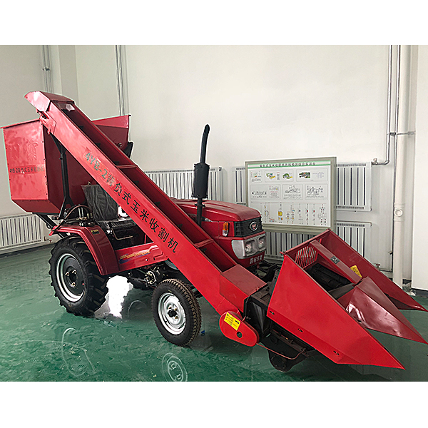
This tr*ning is based on the original vehicle of the new 4YB-2 backpack corn harvester. It is combined with the teaching and tr*ning troubleshooting teaching board to understand the troubleshooting of the entire vehicle. Understand the structural principles and structural components of the vehicle. There is no damage to the entire vehicle and all systems are functioning normally.
Host indicators:
Brand new 4YB-2 backpack corn harvester/two-row green storage corn combine harvester (power: 18 horsepower)
Project performance parameters Project performance parameters
Machine model 4YB-2 Gr*n loss ≤ 2%
Machine type Suspended corn harvester Gr*n crushing rate ≤ 1%
Supported power 18 HP Cutting length pass rate ≥ 90%
Number of harvest rows 2 rows Stem crushing and return type Rotary cutting type
Working range Row spacing 50-80 cm Ear box volume 0.96 cubic meters
Operation efficiency 3-5 The weight of the whole machine is 600 kg per mu/hour.
The ear loss rate is ≤3%. Overall dimensions of the harvester (length x width x height) 45001300x2650 (mm)
2. The whole vehicle electronic control (electrical) system tr*ning bench (1 set)
1. The whole vehicle Functions of the electronic control (electrical) system tr*ning bench:
(1) The vehicle electronic control (electrical) system tr*ning bench is used for teaching and tr*ning of the vehicle electronic control (electrical) system, including the vehicle electronic control system part: engine Electronic control (electrical) system, lighting and body electrical system;
(2) Measurement panel: The circuit diagram on the panel is completely designed according to the original circuit diagram, and a 4mm measuring point is installed to measure and analyze the electronic control system signal;
(3) Fault setting System: Various types of fault settings and fault simulations can be performed, including open circuits, short circuits, intermittent faults, inaccurate signals, etc.;
(4) Each system operates normally, ret*ning the complete power transmission system and control system.
(5) The inspection console is connected to the entire vehicle through aviation plugs and connecting cables, m*nt*ning all functions of the original vehicle. The inspection console can be removed and the vehicle can drive normally.
(6) The movable "detection operating table" can conduct testing tr*ning for each control system separately.
(7) The inspection console panel is made of 4mm thick high-grade aluminum-plastic panels that are corrosion-resistant, impact-resistant, pollution-resistant, fire-proof, and moisture-proof. The surface is sprayed with primer using a special process; the panel is UV-printed with color circuit diagrams that will never fade; Students can intuitively compare the circuit diagram and the original vehicle system to understand and analyze the working principles of each control system.
(8) There are detection terminals installed on the detection console panel, and the detection tr*ning of the original vehicle electrical control system can be carried out directly on the panel.
(9) Vehicle m*ntenance and rep*r operations can be realized.
(10) It can realize vehicle disassembly and assembly and real vehicle working condition demonstration.
(11) The base part of the inspection console is welded with a steel structure, and the surface of the bench is p*nted using a baking process, with a universal self-locking caster device.
(12) Mechanical assembly and fitter assembly virtual simulation software: This software is developed based on unity3d, with optional 6-level image quality. It is equipped with the design and virtual disassembly and assembly of reducers and shafting structures, the design and simulation of common mechanical mechanisms , and an institutional resource library. , a typical mechanical mechanism (virtual disassembly and assembly of a gasoline engine), the software is a whole software and cannot be individual resources.
A. Reducer design and virtual disassembly interface can choose worm gear bevel gear reducer, two-stage expanded cylindrical gear reducer, bevel cylindrical gear reducer, coaxial cylindrical gear reducer, bevel gear reducer, and one-stage cylindrical gear reducer. Gear reducer.
Worm bevel gear reducer: After entering the software, the assembly content is automatically played. Each step in the video has a text description
. Secondary expandable cylindrical gear reducer: After entering the software, the content is played in the form of a video. The video content should include: Part name ( Scan the QR code to see the names of parts), disassembly and assembly demonstration (including disassembly and assembly), virtual disassembly (including overall, low-speed shaft, medium-speed shaft, high-speed shaft, box cover, box seat)
conical cylindrical gear reducer, Coaxial cylindrical gear reducer, bevel gear reducer, first-level cylindrical gear reducer: click to enter and automatically jump to the edrawings interface. The models are all three-dimensional models . By clicking on the parts, the names of the parts are displayed, and the 360° view is av*lable Rotate, enlarge, reduce, translate, and at the same time, the entire reducer can be disassembled and assembled through the moving parts function. At the same time, you can select the home button to return to the original state of the reducer. The bevel gear reducer and the first-stage cylindrical gear reducer have added the function of inserting a cross section, and the cross section can be freely dragged to observe the internal structure of the reducer.
B. Shaft structure design and virtual disassembly and assembly interface optional parts recognition, disassembly and assembly demonstration, and actual operation. 1. Parts recognition: three-dimensional model and part name
including helical gear, non-hole end cover, coupling, coupling key, shaft, gear key, hole end cover, shaft sleeve, deep groove ball bearing, any All parts can be rotated 360° 2. Disassembly and assembly demonstration: There are 2 built-in cases. When you move the mouse to the position of a cert*n part (except the base and bearing seat), the part will automatically enlarge and the name of the part will be displayed. It is equipped with disassembly and Assembly button, the function is to automatically complete the disassembly and assembly of the shaft system structure by the software. All three-dimensional scenes can be rotated, enlarged, reduced and translated 360° in all directions. 3. Practical operation: The three-dimensional parts are neatly placed on the table. The students manually select the corresponding parts and move them to the shaft system structure. The parts can be installed only when they are placed in the correct order and in the correct position. There is a restart button to facilitate students to restart. Conduct virtual experiments. When you move the mouse to a cert*n part position (except the base and bearing seat), the part will automatically enlarge and the part name will be displayed. C. Common machinery
Mechanism design and simulation: optional hinged four-bar mechanism design and analysis, I\II type crank rocker mechanism design and analysis, offset crank slider mechanism design and analysis, crank swing guide rod mechanism design and analysis, hinged four-bar mechanism trajectory Comprehensive, eccentric linear-acting roller push rod cam , centering direct-acting flat bottom push rod cam .
1. Each mechanism should be able to input corresponding parameters, and the software can automatically calculate the parameters, and can perform motion simulation and automatically draw curves.
D. The mechanism resource library includes 11 types of planar link mechanisms, 5 types of cam mechanisms, 6 types of gear mechanisms, 8 types of transmission mechanisms, 11 types of tightening mechanisms, 6 types of gear tr*n mechanisms, and 8 types of other mechanisms ( mechanical equipment simulation)
E , virtual disassembly and assembly of gasoline engines, optional crankcase assembly and disassembly demonstration, crankcase virtual assembly, valve tr*n assembly and disassembly demonstration, valve tr*n virtual assembly
1. Crankcase assembly and disassembly demonstration and valve tr*n assembly and disassembly demonstration both have disassembly button, assembly button, restart, and decomposition observation button. When the mouse is moved to a cert*n part position, the part will automatically enlarge and the part name will be displayed. The software automatically completes the disassembly and assembly of the shaft system structure. When using the decomposition observation button, the 3D model of the crankcase or gas distribution system automatically displays an exploded view, which can be rotated, enlarged, reduced, and translated 360°.
2. The 3D parts of the crankcase virtual assembly and the gas distribution system virtual assembly are neatly arranged When placed on the desktop, students manually select the corresponding parts and move them to the mechanism. The parts can be installed only when they are placed in the correct order and in the correct position. There is a restart button to facilitate students to re-perform the virtual experiment. When you move the mouse to cert*n part locations, the part names are automatically displayed.


 Wechat scan code follow us
