Shanghai Daiyu Education Equipment Manufacturing Co., Ltd.
Language:


The simulated driving tr*ning system can realize the three major module functions of teaching, tr*ning and assessment. It is a full-featured driver comprehensive tr*ning system for urban r*l transit vehicles . It can truly simulate the various operating environments and working conditions of urban r*l transit vehicles. driving controls, operating characteristics, operating conditions and audio-visual environment.
The simulated driving tr*ning system covers the operation skills tr*ning and assessment functions of new drivers and active drivers, enabling tr*nees to comprehensively, comprehensively and systematically master the basic knowledge and theoretical regulations of urban r*l transit vehicles, and be equipped with basic operations, emergency fault handling, abnormal Ability to drive and handle emergencies.
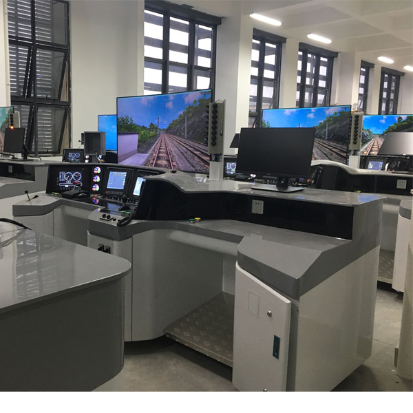
2. Simulated driving tr*ning system
The basic driving simulator provides an economical, practical, reliable and effective intermediate learning platform for students to enter the full-featured driving simulator. Through basic simulator driving, students can become familiar with basic information such as driver consoles, instruments, and display devices, and master basic operating procedures, laying a reliable foundation for more in-depth tr*ning on full-featured simulators.
The basic driving simulator has the following features:
1. Equipped with a driver console that is consistent with the real urban r*l transit vehicle console;
2. Have complete control and display equipment consistent with the real console equipment;
3. Able to realistically reproduce the operating conditions, handling characteristics, traction/braking characteristics and other characteristics of urban r*l transit vehicles in different operating environments and working conditions from the aspects of vision, hearing, and control reality;
4. Ability to simulate various faults and emergencies related to operating lines and urban r*l transit vehicle operations, and enable troubleshooting and emergency drills based on console hardware and multi-functional fault handling screens;
5. Able to realistically simulate all sound effects when urban r*l transit vehicles are running, including external sounds and vehicle internal sounds at different speeds and operating environments;
6. Adopt a full-featured CGI visual system for simulated driving and use a large-size LCD device as visual output;
7. It can be used online under the supervision of the teacher monitoring and control system, and can also be used as an independent drill system.
3. List of m*n equipment
|
serial number |
Device name |
Technical Parameters |
quantity |
unit |
Remark |
|
1 |
Console body |
The imitation tr*n driver's console is made according to the 1:1 simulation of the real vehicle console; the size, appearance, layout, material, and color are consistent with the real vehicle console. The console includes the driver's controller, speedometer, TCMS-MMI display, ATC-MMI display, various buttons, and indicator light panels. |
1 |
set |
|
|
2 |
Student ch*r |
Meet simulator needs. |
1 |
open |
|
|
3 |
TCMS-MMI display |
No less than the following parameters: M*n technical parameter requirements of the monitor: (1) Display mode: TFT LCD display (2) Screen size: consistent with the real car (3) Resolution: ≥1024×768 (4) Color: ≥24bits (5) Brightness: ≥250cd/m2 (6) Contrast ratio: 400:1 The m*n technical parameter requirements of the touch screen: (1) Touch screen type: Resistive screen (2) Size: consistent with the real car (3) Resolution: ≥4096×4096 (4) Response time: < 16ms (5) Transmittance: ≥92% (6) Sensing force: ≤85g force |
1 |
set |
|
|
4 |
ATC-MMI display |
No less than the following parameters: M*n technical parameter requirements of the monitor: (1) Display mode: TFT LCD display (2) Screen size: consistent with the real car (3) Resolution: ≥1024×768 (4) Color: ≥24bits (5) Brightness: ≥250cd/m2 (6) Contrast ratio: 400:1 The m*n technical parameter requirements of the touch screen: (1) Touch screen type: Resistive screen (2) Size: consistent with the real car (3) Resolution: ≥4096×4096 (4) Response time: < 16ms (5) Transmittance: ≥92% (6) Sensing force: ≤85g force |
1 |
set |
|
|
5 |
switch button indicator light |
The switches, buttons, and indicators are consistent in size, appearance, color, and feel with those on the prototype car, and have the same functions and control logic. Drivers can realize driving simulation and control of the vehicle by manipulating these devices. |
1 |
set |
|
|
6 |
car radio |
Provide wired communication function. Copy the original product and implement basic voice communication functions in a wired manner to meet the simulation communication needs of the simulator. |
1 |
set |
|
|
7 |
visual computer |
No less than the following parameters: CPU: Intel® Core I5; Memory: ≥4GB DDR3; Solid state drive: ≥120GB; Graphics card: independent graphics card, memory 2G DDR5; |
1 |
tower |
|
|
8 |
visual display |
Not less than the following parameters: 43-inch LCD TV Backlight type: LED (Slim Direct L) Resolution: 192×1080 (FHD) Brightness: 300cd/㎡ Viewing angle: 178×178 Response time: 6ms Speaker power: 5W×2 HDMI input: 1 way Computer audio input: 1 channel |
1 |
tower |
|
|
9 |
Virtual device and troubleshooting screen |
No less than the following parameters: Monitor: 19-inch infrared touch LCD screen Best resolution: 1280x1024 Number of color bits: 24bit Contrast ratio: 1000:1 Brightness: 300cd/㎡ Viewing angle: 176/170° Glass thickness: 4.5mm Transmittance: >90% |
1 |
tower |
|
|
10 |
Acquisition System |
No less than the following parameters: Built-in microcomputer measurement and control and communication system can realize data collection , output and communication functions. digital input Channel:>120 Voltage range: 5-110V (dc) Response time: ≤10mS digital output Channel:>60 Current range: 1A/DC24V Response time: ≤10mS Analog input Channel:>3 channels Voltage range: 0-10V Response time: ≤10mS Analog output Channel:>3 channels Voltage range: 0-10V/10mA Current loop: 0-30mA/7V Response time: ≤10mS Communication: TCP/IP, RS485 Protocol: Support MODBus, SMBus |
1 |
set |
|
|
11 |
8-port switch |
Not less than the following parameters: Port: 8 10/100Base-TX Ethernet ports, 1 10/100/1000Base-T Ethernet port, 1 multiplexed Gigabit Combo SFP; MAC address table: supports 8K MAC addresses surface; |
1 |
tower |
|
|
12 |
Teacher desks and ch*rs |
Workbench: 1200×600×750mm, supporting seats: 580×500×800mm, steel-wood structure; |
1 |
set |
Only 1 set is provided for the whole room |
|
13 |
Faculty Computer |
No less than the following parameters: CPU: Intel® Core I5 Memory: ≥4GB DDR3 Solid state drive: ≥120GB Graphics card: independent graphics card, supports 2-screen display, 2G DDR5 memory Includes: USB keyboard, USB mouse |
1 |
tower |
|
|
14 |
Instructor monitor |
No less than the following parameters: (1) Screen size: 19 inches; (2) Maximum resolution: 1440×900 (3) Brightness: 300 cd/m2; (4) Response time: 5 milliseconds; (5) Interface: VGA; |
1 |
tower |
|
|
15 |
Cables and integrated wiring |
Includes cables, cable troughs, power modules, distribution boxes, other consumables and integrated wiring used in the system. Equipped with a virtual simulation system for electricity safety and electric shock first *d. The software uses a virtual screen that combines two-dimensional and three-dimensional to teach students the safety and first *d methods of electricity use. The software has single-phase electric shock, two-phase electric shock, step electric shock, and low-voltage electric shock. Principles of first *d, high-voltage electric shock first *d, artificial respiration rescue method, hand-holding breathing rescue method, chest cardiac compression and rescue method, etc. Principles of single-phase electric shock rep*r live disconnection, socket electric shock rep*r, outdoor electric shock and other principle demonstrations. The teaching of low-voltage electric shock and high-voltage electric shock m*nly expl*ns and demonstrates to students how to rescue people who are suffering from low-voltage electric shock or high-voltage electric shock. Artificial respiration rescue method, hand-holding breathing rescue method, and chest cardiac compression rescue method are demonstrated using 3D virtual simulation technology. After rendering and Polish it to make the model look like the real part and look realistic. Through practical tr*ning, students can be educated on the safe use of electricity in the tr*ning room, improve students' safety awareness, and enable students to learn some self-rescue methods, so that students can take cert*n safety measures to protect themselves when encountering danger, and become familiar with various Causes of electrical accidents and practical measures to deal with them to reduce the occurrence of electrical accidents. Demo and copyright certificate provided |
1 |
set |
|
|
16 |
Run simulation software |
1. The basic simulator operation simulation software should be able to simulate the operating conditions, handling characteristics, traction/braking characteristics and other characteristics of Chengdu Metro Line 2 tr*ns under various operating environments and working conditions. 2. Accurate and realistic traction calculation: should be based on simulated subway tr*n model parameters (subway tr*n type, vehicle information, number of vehicles, etc.), line parameters (curves, ramps, adhesive systems), weather conditions (heavy fog, heavy snow, heavy r*n, etc.) ) and other data to perform traction calculations to correctly simulate the running speed and conditions of subway tr*ns; 3. Complete control logic simulation: The software should synchronously simulate the m*n control logic principles related to the subway tr*n based on the subway tr*n driver's manipulation and changes in the current operating conditions, which is completely consistent with the real subway tr*n logic; 4. Subway tr*n logic simulation: Correct subway tr*n logic operations should be performed through various controls on the operating console, including working logic simulation of subway tr*n control logic such as power modules, pantographs, m*n circuit breakers, traction logic, and braking logic. And the processing is completely consistent with the logic of real subway tr*ns. 5. Three-meter simulation software (demo and copyright certificate provided): This software is in apk format and can be used on PC or mobile terminals. The functions of this software are: measurement of resistance and measurement of AC voltage ( Measuring the transformer, if the multimeter burns out when measuring the transformer, black smoke will appear and the multimeter can be reset), transistor polarity judgment, DC voltage measurement (the light will turn on when the ammeter is turned on), DC current measurement, and capacitance is good. Bad judgment. This software can drag the red and black pen tips at will. When the two pen tips are dragged and positioned on the object to be measured, a red circle will be displayed. If the positioning is not accurate, no red circle will be displayed, and when incorrect operations are performed (such as the wrong range selected, If the measured data is wrong, etc.), the meter pointer will be unresponsive, prompting errors and re-measurement, etc. This multimeter can select AC voltage range, DC voltage range, resistance range, current range, resistance adjustment to 0, and can enlarge the display data. Clearly view the measured data size. Students can learn the correct use of multimeters through this software. Virtual multimeter parameters: AC voltage range points: 10, 50, 250, 1000; DC voltage range points: 0.25, 1, 2.5, 10, 50, 250, 1000; Ohm range points: x1, x10,,100 ,,1000,,1K,x10K,x100K; Ammeter range: 50μa, 0.5, 5, 50, 500; BATT: 1.2-3.6V, RL=12Ω; BUZZ: R×3; Infrared emission detection function: vertical angle ± 15° distance 1-30cm; triode measuring hole |
1 |
set |
|
|
17 |
Troubleshooting simulation software |
1. The fault handling simulation software should have the functions of normal driving tr*ning and fault and emergency incident handling tr*ning, and be equipped with a 19-inch multi-functional fault handling screen (including a virtual subway tr*n equipment simulation system) for fault and emergency incident handling tr*ning. Function. 2. The fault handling system software adopts a database fault/emergency management mechanism. All fault/emergency information is stored in the system database in the form of data instead of customizing faults/emergency events in the program code. 3. The fault handling simulation software should use a graphical display method to simulate the status of relevant equipment and components outside the cab, and be able to perform interactive operations and fault handling functions on these devices. The virtual tr*n equipment corresponds to the real equipment of the real tr*n and has consistent external representation and internal logic. 4. The fault handling simulation software should have the ability to store multiple fault data and emergencies. Faults and abnormal situations can all be run on the driving simulation tr*ning system. The system software can be pre-set in the course or the instructor can set up emergencies and abnormal situations as needed, and the visual system can respond immediately. |
1 |
set |
|
|
18 |
Visual simulation software |
1. The visual simulation software should be able to simulate scenes related to all areas that subway tr*ns can reach. These areas include: all m*n lines, station depot lines, parking lines, parking lines, entrance and exit section contact lines, etc. The visual system includes all static and dynamic scenery within the driver's field of view when the subway tr*n runs in both directions in the above area. These scenery m*nly include: (1) Track (m*n line and depot): r*ls, intersections, switches, roadbed, track bed, green paving; (2) Catenary (3) Line side equipment (4) Platform (5) Scenery along the route (6) Depot/depot (including various buildings and equipment in the depot ) (7) Other subway tr*n vehicles All the above visual scenes are modeled in strict accordance with the recorded line scenes and line engineering data (including plan and longitudinal sections) to ensure that the lines, equipment, etc. are highly consistent with the actual lines, and the surrounding scenes are basically consistent with the actual situation. Daytime, nighttime, dusk or dawn images with sufficient image det*l to allow drivers to identify major landmarks around stations, terr*n and lines. The image det*ls should also allow drivers to successfully complete vehicle operations such as visual entry and exit; 2. The simulation scene of the visual simulation software is displayed on the large display screen in front of the control console, and the scenes, stations, signals and controls on the line are kept running synchronously. 3. For the visual line, Chengdu Metro Line 2 is used for three-dimensional model production to generate a simulated operating line scene. The effect should be almost exactly the same as the actual line scene. At the same time, the software should be able to simulate abnormal driving emergencies, such as power outages in the station, pedestrians lying on the track, flooded track beds, fires on the platform, broken tracks, etc., and can synchronously update the display view according to different traction calculation speeds. |
1 |
set |
|
|
19 |
Sound simulation software |
The sound simulation software has the same functions as the full-featured driving simulation software. Able to simulate various sounds when a subway tr*n is running, including sounds inside and outside the subway tr*n; 1. Sounds outside the vehicle include: 1) Wind noise when the vehicle is running; 2) The track sound of the switch; 3) Braking and emergency braking sounds; 4) The sound of impact with obstacles; such as the impact of the coupler connection between two vehicles during rescue, and the sound of a vehicle hitting a pedestrian who fell off the road; 5) Thunder (should be consistent with the visual effects - first there is lightning, then thunder); |
1 |
set |
|
|
20 |
Communication simulation software |
The simulated driver communicates with the dispatcher (instructor instead); The simulated driver communicates with the depot dispatcher (instructor instead); 3. Teachers can choose communication roles in the teacher system software. |
1 |
set |
|
|
twenty one |
CCTV simulation software |
Simulate virtual subway tr*n passenger room video surveillance function. Practical tr*ning safety education virtual simulation software: The software is based on C# and JS language programming design. Users can choose different interactive interface sizes according to computer configuration. Six levels of image quality can be selected, including smooth image quality, medium image quality, and perfect image quality. More than ten types of shafting mechanisms, including gear shafting and worm shafting, can be selected for installation, disassembly, assembly, parts measurement, and assessment. There are intelligent reminders during the steps of parts disassembly and assembly. The models in the software are all 3D models, produced by 3Dmax, and have been rendered and polished to make the models look the same as real parts. There is a non-standard parts library, Standard parts library and measurement tool library for disassembly and assembly selection. The software is equipped with integrated electronic experiment assessment questions and instructions for the purpose, steps, and requirements of the experiment. When using the assessment function, the software randomly generates questions for students to answer, and gives assessment scores when students finish answering the questions. This software can rotate, zoom in and out in all directions to view its det*ls. Demo and copyright certificate provided. |
1 |
set |
|
|
twenty two |
Faculty software |
Course management, teaching task release, operation monitoring, assessment and evaluation, equipment management and other functions. Teacher teaching design system: This software is in apk format and can be used on PC or mobile. This software can manually set faults or automatically set faults. This software can manually set faults by selecting the green box in the circuit diagram. points (up to 39 fault points can be set), or the system can automatically set one random fault point, two random fault points, three random fault points, four fault points randomly, and five fault points randomly. Settings, this software has toolbox, component library, magnifying glass, circuit diagram and other functions. You can select a multimeter for testing through the toolbox, select appropriate components through the component library, and clearly understand each component and circuit through the magnifying glass. This software allows students to understand the working principle and circuit structure of the motor star-delta start control circuit through the setting of faults in the motor star-delta start control circuit and various investigations. Demo and copyright certificate provided. |
1 |
set |
Only 1 set is provided for the whole room |
 Wechat scan code follow us

24-hour hotline+86 18916464525

Phone18916464525
ADD:Factory 414, District A, No. 6, Chongnan Road, Songjiang Science and Technology Park, Shanghai ICP: Sitemap