1. AC power supply: single-phase AC 2200 V±10% 50Hz;
2. Relative temperature: -10~50℃;
3. Relative humidity: <85% (25℃)
4. Overall dimensions: about 1400mm×700mm×820mm;
5. Power consumption of the whole machine: ≤1.0 kVA;
6. Safety protection measures: The desktop of the tr*ning platform is made of high-density board with high insulation, high strength and high temperature resistance. It has grounding protection and leakage protection functions, and its safety complies with relevant national standards. Uses high-insulation safety sockets and high-strength safety experimental wires with insulating sheaths.
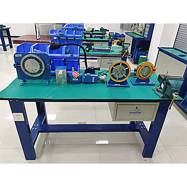
Functional features
1. Can carry out disassembly and assembly experiments on industrial hydraulic components.
2. In order to reduce the noise caused by collision during disassembly and assembly, anti-static leather mats are l*d on the table.
3. There is also a small component box on the table to prevent the loss of parts.
4. A disassembly and assembly pad is designed to prevent damage to the desktop during disassembly and assembly.
5. Equipped with drawers, machine tool lamps, and AC power sockets.
6. The tr*ning table is made of metal frame, the surface is treated with double-layer matte dense texture spray molding process, and comes with two experimental ch*rs.
Configuration list:
1. 1 experimental bench
2. Gear pump (1 BB-B6)
3. Direct-acting relief valve (1 P-B10)
4. Pilot-operated relief valve (1 Y-10B)
5 , Pressure reducing valve (DR10-4-5X10Y 1 piece)
6. Throttle valve (DVP6 1 piece)
7. Speed regulating valve (2FRM5-31B/15QB 1 piece)
8. Hydraulic control check valve (SV10PA1-30 1 piece) )
9. Three-position four-way directional valve (4WE6E61B/CG24N9Z5L 1 piece)
10. Horizontal lever double-acting hydraulic cylinder (MOB40-200 1 piece)
11. Steel tape measure (30CM 1 piece)
12. Micrometer (0~25mm 1 piece)
13. Circlip pliers (1 set of inner and outer P1ERS)
14. Adjustable wrench (1 set of 6”-150mm)
15. Adjustable wrench (1 set of 10”-250mm)
16. Allen wrench (1 set of JTECH)
17. Disassembly Install the pad (one component is disassembled and assembled on the pad
) 18. Rubber pad (1 piece)
19. Oil pot (1 piece for 5 pounds)
20. Three-plug power supply (1 piece)
21. Machine tool lamp (1 piece)
22. Component box (1)
23. Bench vise (1)
24. Toolbox (1)
25. Virtual simulation tr*ning software
Hydraulic and pneumatic transmission design and control virtual simulation software
This software is developed based on unity3d, and the software uses three-dimensional In the form of roaming, the movement can be controlled by the keyboard, and the camera direction can be controlled by the mouse. The interface has homepage, help, full screen, component recognition, loop construction, key component testing, and typical system testing interfaces.
1. Component identification adopts the form of automatic playback. , introduces the m*lbox, liquid level gauge, oil pump unit on the equipment (the pop-up hydraulic symbols, principles and introduction are introduced here, click OK to enter the next introduction), valve frame, pressure gauge, sensor , etc.
2. Component disassembly is divided into Learning mode and assessment mode, built-in electromagnetic reversing valve, plate relief valve, plunger pump, filter valve, electro-hydraulic servo valve. In the learning mode, the disassembly sequence is prompted and highlighted. In the assessment mode, there are no prompts for disassembly and installation. When the disassembly and assembly sequence is wrong, the next step of disassembly and assembly will no longer be possible. The toolbar is equipped with draggable seals, pumps, valves, oil filters, hex wrenches, pipe wrenches, adjustable wrenches, dead wrenches, and M5 screws. .
3. The hydraulic components are equipped with one-way valve (hydraulic control, poppet valve core, ball valve core), directional valve m*n structure (O type, Y type, H type), hydraulic cylinder (assembled plunger, double-acting single outlet) rod, double-action double-output rod, single-action double-output rod, single-action single-output rod), etc., each construction experiment adopts a graphical method, and is constructed by dragging the set graphics, graphics library There are confusing graphics.
4. Hydraulic selection is based on the hydraulic schematic diagram, and then selects the pump’s nominal displacement (12 items, including 11 confusing items), pressure level (5 items, including 4 confusing items), and electromagnetic relief. Valve selection (3 specifications, 3 pressure levels, and 3 flow levels, all with confusing items), oil filter selection (multiple choices include confusing items), servo valve selection (multiple choices include confusing items) . If you make an incorrect selection, the system will automatically prompt you for the correct answer. After selecting, drag the corresponding tool to the highlighted area according to the prompts.
5. Circuit inspection is done by selecting the correct accessories, including the selection of sealing rings, checking valve switches, etc. Then proceed to the next step to turn on the machine. Follow the prompts to turn on the machine. After turning on the machine, enter the monitoring interface. Turn on the equipment one by one according to the prompts. The prompts are in the form of text and button highlighting.
6. Hydraulic cylinder pressure test Enter the experiment through the test button on the background interface and gradually analyze To start friction test, start friction force, parameter setting, start test, draw curve, stop test.
7. Typical system tests are divided into trial operation, stage response test and frequency response test. The above tests are all conducted through the background monitoring interface.
8. The software must be able to rotate, zoom in and out in all directions to view its det*ls. And the same platform as a whole cannot be displayed as separate resources.
Microcontroller , PLC programmable design and control virtual simulation software.
This software is developed based on unity3d. It has built-in task books and experimental prompts. It adopts the form of three-dimensional roaming. Movement can be controlled by the keyboard, the direction of the lens can be controlled by the mouse, and the distance of the picture can be controlled by the mouse wheel, which can be 360 degrees. Rotating, three-dimensional wall p*nted with electrical diagrams.
1. Equipment component assembly: Follow the highlighted prompts to find the component control rack. You can drag components from the component library according to the electrical component layout diagram and place them on the component control rack. The component library is equipped with control panels, switching power supplies, micro relays, and plcs. , frequency converter, stepper motor , AC motor, servo motor, servo driver, stepper driver, interface board, operation panel, circuit breaker, servo motor interface, digital display voltmeter, there will be a prompt when the selection is wrong.
2. Technical indicator measurement: Select a multimeter to check the servo motor connection cable and the servo driver with BOP panel. Adjust the left and right buttons to the ohm level, drag the black and red test leads and insert them into the R, S, T, U, V, W, and ground phases respectively for testing. For resistance value, according to the highlighted prompt, find the power switch in the scene, drag the pen or multimeter to measure whether the power is on.
3) Electrical component connection: According to the electrical wiring diagram, connect the power line and control line, highlight the interface, connect the driver, interface board, power line, servo motor, encoder, PLC, and relay in order, and turn on the m*n power supply After turning on the switch, servo power switch, and faulty circuit switch, a fault code will be prompted, and you can select the cause of the fault from three items.
4) Parameter adjustment test: Turn on the power to adjust the speed, set the driver parameters according to the requirements of the mission statement, perform inching control/analog speed adjustment/multi-stage speed control, and observe the three-dimensional servo motor motion control. Select any of the 6 PLC programs and then adjust the servo drive analog speed. The PLC parameters are adjustable. Set the drive parameters and enter the three-dimensional servo motor motion control interface and electrical display interface. The operation panel is equipped with servo start, low speed, medium Speed, high speed, servo stop, torque limit, abnormal reset, forward/reverse rotation selection, 0-10 sliding control (the electrical panel displays the value in real time).
5) Inspect the three-dimensional virtual simulation machine of the servo system mask machine, observe its structure, inject fault points, select multiple fault causes, and locate faults. Connect the fault causes with the corresponding detection and positioning methods, and troubleshoot after selecting the correct ones. Connect the cause of the f*lure with the corresponding solution.
6) Control process plan, optional single machine mode and online mode of inching control/analog speed regulation/multi-stage speed regulation control, call up the control panel, display the operation of 3 production lines, perform real-time control, optional inching, low and medium High speed, start and stop control, adjustable speed. According to the control plan, the system automatically determines the performance of the production line and submits a disclosure record.


 Wechat scan code follow us
