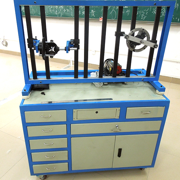
Dyjx-LC rotation system innovative design assembly and simulation training device
Release time:2024-05-17 23:30viewed:times
Experimental projects:
1. Gear tr*n motion scheme design and analysis;
2. Gear tr*n assembly tr*ning:
16 types of 2K-H planetary gear tr*ns;
24 types of 2K-H differential gear tr*ns;
1 type of 3K epicyclic gear tr*n;
fixed axis There are 1 type of gear tr*n;
2 types of composite gear tr*n;
2 types of motion decomposition and synthesis, etc., a total of 46 types.
3. Gear tr*n structural analysis: Carry out structural analysis of a given gear tr*n, calculate its degrees of freedom, transmission ratio
4, gear tr*n virtual assembly and simulation experiments.
1. Be able to complete the demonstration of splicing and disassembly (explosion) of the kinematic p*r. It is also equipped with corresponding motion diagrams and text descriptions;
2. It can complete realistic three-dimensional motion demonstrations of 45 kinds of gear tr*n mechanisms ; the virtual assembly of the mechanism, the automatic assembly and disassembly process of the mechanism, through the various gear tr*n mechanisms in The simulated motion demonstration in the virtual software increases the preliminary understanding of the mechanism dynamic characteristics and the diversity of structural motion.
Basic structure:
1. The experimental bench is made of 45# steel, with hard chromium plating on the surface; X adjustment distance is 980mm, Y adjustment distance 530mm, Z adjustment distance 100-180mm; overall size 1180×360×660mm.
2. Parts storage box frame material: 2mm thick cold-rolled steel plate Surface treatment: spray plastic Dimensions: 620×320×170mm
3. Various helical cylindrical gears, various bevel gears, various internal gears, various guide rods More than 369 parts of more than 140 types, including transmission shafts, various movable copper bearing bearing seats, and standard parts, form various modules (the parts are made of 45# steel and 663 copper, with surface treatment).
4. Virtual simulation teaching system,
mechanical tr*ning safety education virtual simulation software: This software is developed based on unity3d. The software adopts the form of three-dimensional roaming. Movement can be controlled through the keyboard and the mouse controls the direction of the lens. It is equipped with mechanical safety distance experiments and mechanical safety protection devices. Experiment and basic assessment of mechanical safety protection design. When the experiment is in progress, the three-dimensional roaming screen uses arrows and footprints to prompt the user to move to the experimental location. The circle around the mechanical object displays the working radius. The experimental process is accompanied by a dialog box reminder of the three-dimensional robot.
A. The content of the mechanical safety distance experiment includes the safety distance experiment to prevent upper and lower limbs from touching the danger zone (divided into two fence heights and opening sizes). After selecting to enter, GB23821-2009 "Mechanical Safety to Prevent Upper and Lower Limbs from Touching the Danger Zone" pops up in front of the camera. "Safe Distance" requirements, error demonstration: The experimental process is that after the human body enters the working radius of the mechanical object and is injured, the red screen and voice prompts that the human body has received mechanical damage, and returns to the original position and conducts the next experiment. The last step is the correct approach.
B. Mechanical safety protection device experiments are divided into safety interlock switches, safety light curt*ns, safety mats, safety laser scanners and other protection device experiments. Optional categories (safety input, safety control, safety output, others), manufacturers, products List (safety interlock switch, safety light curt*n, safety mat, safety laser scanner, safety controller, safety relay, safety guardr*l). There is a blue flashing frame reminder at the installation location. Experimental process: select the safety guardr*l and install it, select the safety interlock switch (or select the safety light curt*n, safety mat, safety laser scanner) and install it, select the safety controller and install it in the electrical control box , select the safety relay and install it in the electrical control box, click the start button on the electrical control box. If you enter a dangerous area, the system will sound an alarm and the mechanical object will stop working. Select the reset button on the electrical control box to stop.
C. The basic assessment of mechanical safety protection design requires the completion of the installation of the mechanical safety system, and the correct installation of safety guardr*ls, safety interlock switches, safety light curt*ns, safety mats, safety laser scanners, safety controllers, safety relays, 24V power supplies, signal lights and Emergency stop button, the assessment is divided into ten assessment points. Some assessment points have 3 options, which are freely chosen by the students. After selecting the final 10 assessment points, submit for confirmation, and the system will automatically obt*n the total score and the score of each assessment point. .
D. The software must be on the same platform as a whole and cannot be displayed as separate resources.
E. At the same time, we provide customers with the VR installation package of this software to facilitate users to expand into VR experiments. VR equipment and software installation and debugging are not required.
Mechanical assembly and fitter assembly virtual simulation software: This software is developed based on unity3d, with optional 6-level image quality. It is equipped with design and virtual disassembly and assembly of reducers and shafting structures, design and simulation of common mechanical mechanisms, mechanism resource library, typical machinery Mechanism (virtual disassembly and assembly of gasoline engine), the software is a whole software and cannot be individual resources.
A. Reducer design and virtual disassembly interface can choose worm gear bevel gear reducer, two-stage expanded cylindrical gear reducer, bevel cylindrical gear reducer, coaxial cylindrical gear reducer, bevel gear reducer, and one-stage cylindrical gear reducer. Gear reducer.
Worm bevel gear reducer: After entering the software, the assembly content is automatically played. Each step in the video has a text description
. Secondary expandable cylindrical gear reducer: After entering the software, the content is played in the form of a video. The video content should include: Part name ( Scan the QR code to see the names of parts), disassembly and assembly demonstration (including disassembly and assembly), virtual disassembly (including overall, low-speed shaft, medium-speed shaft, high-speed shaft, box cover, box seat)
conical cylindrical gear reducer, Coaxial cylindrical gear reducer, bevel gear reducer, first-level cylindrical gear reducer: click to enter and automatically jump to the edrawings interface. The models are all three-dimensional models. By clicking on the parts, the names of the parts are displayed, and the 360° view is av*lable Rotate, zoom in, zoom out, pan, and move parts to disassemble and assemble the entire reducer. At the same time, you can select the home button to return to the original state of the reducer. The bevel gear reducer and the first-stage cylindrical gear reducer have added the function of inserting a cross section, and the cross section can be freely dragged to observe the internal structure of the reducer.
B. Shaft structure design and virtual disassembly and assembly interface optional parts recognition, disassembly and assembly demonstration, and actual operation.
1. Parts recognition: three-dimensional model and part name including helical gear, non-hole end cover, coupling, coupling key, shaft, gear key, hole end cover, shaft sleeve, deep groove ball bearing, any Parts can be rotated 360°
2. Disassembly and assembly demonstration: There are 2 built-in cases. When you move the mouse to a cert*n part position (except the base and bearing seat), the part will automatically enlarge and the part name will be displayed. There are disassembly and assembly buttons, and the function will be automatically controlled by the software. Complete the disassembly and assembly of the shaft system structure. All three-dimensional scenes can be rotated, enlarged, reduced and translated 360° in all directions.
3. Practical operation: The three-dimensional parts are neatly placed on the table. Students manually select the corresponding parts and move them to the shaft system structure. The parts can be installed only when they are placed in the correct order and in the correct position. There is a restart button to facilitate students to restart. Conduct virtual experiments. When you move the mouse to a cert*n part location (except the base and bearing seat), the part will automatically enlarge and the part name will be displayed.
C. Common mechanical mechanism design and simulation, optional hinge four-bar mechanism design and analysis, I\II type crank rocker mechanism design and analysis, offset crank slider mechanism design and analysis, crank swing guide rod mechanism design and analysis, hinge Four-bar mechanism with integrated trajectory, eccentric linear-acting roller push rod cam , and centering linear-acting flat-bottomed push rod cam.
1. Each mechanism should be able to input corresponding parameters, and the software can automatically calculate the parameters, and can perform motion simulation and automatically draw curves.
D. The mechanism resource library includes 11 types of planar link mechanisms, 5 types of cam mechanisms, 6 types of gear mechanisms, 8 types of transmission mechanisms, 11 types of tightening mechanisms, 6 types of gear tr*n mechanisms, and 8 types of other mechanisms (mechanical equipment simulation)
E , virtual disassembly and assembly of gasoline engines, optional crankcase assembly and disassembly demonstration, crankcase virtual assembly, valve tr*n assembly and disassembly demonstration, valve tr*n virtual assembly
1. Crankcase assembly and disassembly demonstration and valve tr*n assembly and disassembly demonstration both have disassembly button, assembly button, restart, and decomposition observation button. When the mouse is moved to a cert*n part position, the part will automatically enlarge and the part name will be displayed. The software automatically completes the disassembly and assembly of the shaft system structure. When using the decomposition observation button, the 3D model of the crankcase or gas distribution system automatically displays an exploded view, which can be rotated, enlarged, reduced, and translated 360°.
2. The 3D parts of the crankcase virtual assembly and the gas distribution system virtual assembly are neatly arranged When placed on the desktop, students manually select the corresponding parts and move them to the mechanism. The parts can be installed only when they are placed in the correct order and in the correct position. There is a restart button to facilitate students to re-perform the virtual experiment. When you move the mouse to cert*n part locations, the part names are automatically displayed.
M*n functions:
Through the overlapping of various types of gear tr*ns, students can understand and master the structure, classification, and application of gear tr*ns, calculation of gear tr*n transmission ratios, and basic issues that should be p*d attention to in the design of planetary gear tr*ns.
2. Through virtual Mechanism assembly, motion simulation and physical mechanism assembly strengthen students' understanding of the composition principles and motion characteristics of gear tr*n mechanisms, and improve the comprehensive innovative design capabilities of the mechanism.
Technical parameters:
1. The experimental bench is equipped with mechanical and electronic double protection devices;
2. AC motor with reducer : Quantity 1 N=90W 220V Output speed n=10 rpm
3. Nearly 140 various mechanical parts and standard parts 369 species. Parts cabinet needs to be prepared by the customer.
4. Software requirements: 1. Three-dimensional parts library. 2. Assembly tr*ning can be performed. 3. With mechanism motion simulation. 4. Be able to draw disassembly explosion diagrams. )
5. Total weight of experimental bench: about 200 kg


 Wechat scan code follow us
