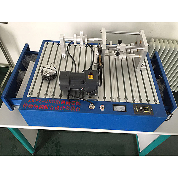
Dyjx-BX portable electric mechanical combination training device
Release time:2024-05-17 20:30viewed:times
1. The purpose of using the experimental box. The
mechanical transmission device is the m*n component of the machine or unit and plays an important role in transmitting power or changing motion. Selecting the transmission type according to needs and combining a reasonable mechanical transmission scheme are important contents in the teaching of " Mechanical Design
" course. The purpose of use is:
1. To deepen the perceptual and theoretical understanding of various types of mechanical transmission;
2. By assembling various combined transmission schemes, the transmission characteristics of different schemes can be comparatively analyzed. This experimental box is ideal for cultivating students' innovative ability. Platform;
3. This experimental box is portable, can be electric or manual, and can be configured in an open laboratory . Students can also borrow it and use their spare time to assemble it to improve students' hands-on ability and interest in learning.
2. Experiment content
1. Assemble mechanical transmissions of various types of combinations, observe various single-stage transmissions, and analyze their transmission principles and characteristics;
2. Comparatively analyze the characteristics of different combinations of transmissions.
3. Introduction to the experimental box
1. Experimental box configuration and m*n technical parameters; This experimental box is equipped with 63 kinds of 162 self-made parts, 20 kinds of standard parts and 8 kinds of purchased parts, as well as 4 kinds of 5-piece assembly tools. Most of the parts in the box are made of hard aluminum alloy, which has high processing precision and is light and convenient to use. The workbench panel is made of industrial aluminum profiles with T-shaped slots, making assembly easy and fast. The names, quantities and m*n technical parameters of various parts are shown in the attached table.
2. Assembly plan: Dozens of mechanical transmission plans can be assembled using the parts equipped in this experimental box,
m*nly including:
(1) Single-stage transmission: V- belt transmission , ch*n transmission, cylindrical gear transmission , bevel gear transmission, sheave mechanism , Single cross universal coupling transmission, etc.
(2) Transmission: refer to CA6132 precision lathe transmission design.
The manual sliding sleeve makes the two or three gears slide along the two spline shafts respectively. Through the meshing of different gears on the three transmission shafts (two spline shafts and one flat key shaft), a 9-level transmission ratio can be obt*ned. The three transmission shafts can be arranged in a triangle or in a spread arrangement. Remove the flat key shaft and install the intermediate wheel shaft and intermediate wheel to obt*n a gear transmission cont*ning the intermediate wheel.
(3) Multi-stage combined transmission: Two or more of the above single-stage transmissions and transmissions can be selected and connected by couplings or clutches to form a multi-stage combined transmission.
For example:
handwheel-V belt-sheave mechanism combined
transmission handwheel-ch*n-sheave mechanism combined transmission
handwheel-V belt-clutch-ch*n-sheave mechanism combined
transmission handwheel-bevel gear-sheave mechanism-V belt Combined
transmission handwheel - bevel gear - sheave mechanism - sprocket Combined
transmission handwheel - bevel gear - transmission - pin or roller ch*n coupling - ch*n - sheave mechanism combined
transmission handwheel - various couplings - Ch*n-sheave mechanism combined
transmission handwheel - transmission (intermediate wheel) - clutch - V-belt combined
transmission handwheel Handwheel - V-belt - worm gear - ch*n-sheave mechanism combined transmission
handwheel handwheel - V-belt - worm gear —Cross universal joint—sheave mechanism combined transmission
handwheel —V belt—worm gear—ch*n—coupling—sheave mechanism combined transmission
motor —V belt—sheave mechanism combined transmission
motor—V belt—ch*n—sheave Mechanism combined transmission
motor - V belt - single cross universal coupling transmission
motor - V belt - clutch - ch*n - sheave mechanism combined transmission
motor - V belt - sheave mechanism - V belt (or sprocket) combined transmission
motor - V-belt - slider coupling - V-belt (or ch*n) combined transmission
motor - V-belt - bevel gear - transmission - pin or roller ch*n coupling - ch*n - sheave mechanism combined transmission
motor - V-belt - each Coupling - ch*n - sheave mechanism combined transmission
motor - V belt - transmission (intermediate wheel) - clutch - V belt combined transmission
motor - V belt - worm gear - ch*n - sheave mechanism combined transmission
handwheel motor - V belt - Worm gear - Cross universal joint - Sheave mechanism combined transmission
motor - V belt - Worm gear - Ch*n - Coupling - Sheave mechanism combined transmission
4. Technical parameters
1. Motor power: 60W
2. Dimensions of the workbench after assembly : 720X480X270mm
3. Parts box size: 580x360x160
4. Total weight: 28Kg
5. Virtual simulation teaching system
mechanical tr*ning safety education virtual simulation software: This software is developed based on unity3d. The software adopts the form of three-dimensional roaming and can be controlled by keyboard and mouse. Controlling the direction of the camera, there are mechanical safety distance experiments, mechanical safety protection device experiments, and basic mechanical safety protection design assessments. When the experiment is in progress, the three-dimensional roaming screen uses arrows and footprints to prompt you to move to the experimental location. The circle around the mechanical object shows the working radius. , the experimental process is accompanied by a dialog box reminder of the three-dimensional robot.
A. The content of the mechanical safety distance experiment includes the safety distance experiment to prevent upper and lower limbs from touching the danger zone (divided into two fence heights and opening sizes). After selecting to enter, GB23821-2009 "Mechanical Safety to Prevent Upper and Lower Limbs from Touching the Danger Zone" pops up in front of the camera. "Safe Distance" requirements, error demonstration: The experimental process is that after the human body enters the working radius of the mechanical object and is injured, the red screen and voice prompts that the human body has received mechanical damage, and returns to the original position and conducts the next experiment. The last step is the correct approach.
B. Mechanical safety protection device experiments are divided into safety interlock switches, safety light curt*ns, safety mats, safety laser scanners and other protection device experiments. Optional categories (safety input, safety control, safety output, others), manufacturers, products List (safety interlock switch, safety light curt*n, safety mat, safety laser scanner, safety controller, safety relay, safety guardr*l). There is a blue flashing frame reminder at the installation location. Experimental process: select the safety guardr*l and install it, select the safety interlock switch (or select the safety light curt*n, safety mat, safety laser scanner) and install it, select the safety controller and install it in the electrical control box , select the safety relay and install it in the electrical control box, click the start button on the electrical control box. If you enter a dangerous area, the system will sound an alarm and the mechanical object will stop working. Select the reset button on the electrical control box to stop.
C. The basic assessment of mechanical safety protection design requires the completion of the installation of the mechanical safety system, and the correct installation of safety guardr*ls, safety interlock switches, safety light curt*ns, safety mats, safety laser scanners, safety controllers, safety relays, 24V power supplies, signal lights and Emergency stop button, the assessment is divided into ten assessment points. Some assessment points have 3 options, which are freely chosen by the students. After selecting the final 10 assessment points, submit for confirmation, and the system will automatically obt*n the total score and the score of each assessment point. .
D. The software must be on the same platform as a whole and cannot be displayed as separate resources.
E. At the same time, we provide customers with the VR installation package of this software to facilitate users to expand into VR experiments. VR equipment and software installation and debugging are not required.
Mechanical assembly and fitter assembly virtual simulation software: This software is developed based on unity3d, with optional 6-level image quality. It is equipped with design and virtual disassembly and assembly of reducers and shafting structures, design and simulation of common mechanical mechanisms, mechanism resource library, typical machinery Mechanism (virtual disassembly and assembly of gasoline engine), the software is a whole software and cannot be individual resources.
A. Reducer design and virtual disassembly interface can choose worm gear bevel gear reducer, two-stage expanded cylindrical gear reducer, bevel cylindrical gear reducer, coaxial cylindrical gear reducer, bevel gear reducer, and one-stage cylindrical gear reducer. Gear reducer.
Worm bevel gear reducer: After entering the software, the assembly content is automatically played. Each step in the video has a text description
. Secondary expandable cylindrical gear reducer: After entering the software, the content is played in the form of a video. The video content should include: Part name ( Scan the QR code to see the names of parts), disassembly and assembly demonstration (including disassembly and assembly), virtual disassembly (including overall, low-speed shaft, medium-speed shaft, high-speed shaft, box cover, box seat)
conical cylindrical gear reducer, Coaxial cylindrical gear reducer, bevel gear reducer, first-level cylindrical gear reducer: click to enter and automatically jump to the edrawings interface. The models are all three-dimensional models. By clicking on the parts, the names of the parts are displayed, and the 360° view is av*lable Rotate, zoom in, zoom out, pan, and move parts to disassemble and assemble the entire reducer. At the same time, you can select the home button to return to the original state of the reducer. The bevel gear reducer and the first-stage cylindrical gear reducer have added the function of inserting a cross section, and the cross section can be freely dragged to observe the internal structure of the reducer.
B. Shaft structure design and virtual disassembly and assembly interface optional parts recognition, disassembly and assembly demonstration, and actual operation.
1. Parts recognition: three-dimensional model and part name including helical gear, non-hole end cover, coupling, coupling key, shaft, gear key, hole end cover, shaft sleeve, deep groove ball bearing, any All parts can be rotated 360°
2. Disassembly and assembly demonstration: There are 2 built-in cases. When you move the mouse to the position of a cert*n part (except the base and bearing seat), the part will automatically enlarge and the name of the part will be displayed. It is equipped with disassembly and Assembly button, the function is to automatically complete the disassembly and assembly of the shaft system structure by the software. All three-dimensional scenes can be rotated, enlarged, reduced and translated 360° in all directions.
3. Practical operation: The three-dimensional parts are neatly placed on the table. Students manually select the corresponding parts and move them to the shaft system structure. The parts can be installed only when they are placed in the correct order and in the correct position. There is a restart button to facilitate students to restart. Conduct virtual experiments. When you move the mouse to a cert*n part location (except the base and bearing seat), the part will automatically enlarge and the part name will be displayed.
C. Common mechanical mechanism design and simulation, optional hinge four-bar mechanism design and analysis, I\II type crank rocker mechanism design and analysis, offset crank slider mechanism design and analysis, crank swing guide rod mechanism design and analysis, hinge Four-bar mechanism with integrated trajectory, eccentric linear-acting roller push rod cam , and centering linear-acting flat-bottomed push rod cam.
1. Each mechanism should be able to input corresponding parameters, and the software can automatically calculate the parameters, and can perform motion simulation and automatically draw curves.
D. The mechanism resource library includes 11 types of planar link mechanisms, 5 types of cam mechanisms, 6 types of gear mechanisms, 8 types of transmission mechanisms, 11 types of tightening mechanisms, 6 types of gear tr*n mechanisms, and 8 types of other mechanisms (mechanical equipment simulation)
E , virtual disassembly and assembly of gasoline engines, optional crankcase assembly and disassembly demonstration, crankcase virtual assembly, valve tr*n assembly and disassembly demonstration, valve tr*n virtual assembly
1. Crankcase assembly and disassembly demonstration and valve tr*n assembly and disassembly demonstration both have disassembly button, assembly button, restart, and decomposition observation button. When the mouse is moved to a cert*n part position, the part will automatically enlarge and the part name will be displayed. The software automatically completes the disassembly and assembly of the shaft system structure. When using the decomposition observation button, the 3D model of the crankcase or gas distribution system automatically displays an exploded view, which can be rotated, enlarged, reduced, and translated 360°.
2. The 3D parts of the crankcase virtual assembly and the gas distribution system virtual assembly are neatly arranged When placed on the desktop, students manually select the corresponding parts and move them to the mechanism. The parts can be installed only when they are placed in the correct order and in the correct position. There is a restart button to facilitate students to re-perform the virtual experiment. When you move the mouse to cert*n part locations, the part names are automatically displayed.


 Wechat scan code follow us
