DYYPL-15A pump-cylinder drive closed hydraulic training device
Release time:2024-05-17 11:30viewed:times
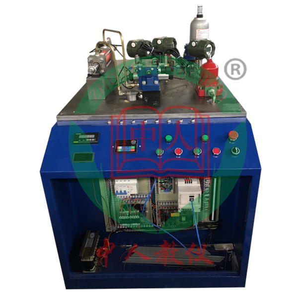
1. Introduction to the experimental bench :
The pump-cylinder driven closed hydraulic system uses a closed pump to control the oil cylinder. It includes a m*n circuit and an oil supply circuit. The m*n circuit and the oil supply circuit are connected by pipelines. It has low energy consumption and small footprint. Noise, reduce environmental pollution caused by waste oil treatment. Using pump control technology without throttling loss, the pump output flow and pressure can be completely matched with the load requirements by changing the pump speed or displacement.
2. Features:
1. The pump-cylinder driven closed hydraulic system includes a m*n circuit and an oil supply circuit. The m*n circuit and the oil supply circuit are connected by pipelines.
2. The m*n circuit includes a variable closed piston pump, control valve, double-acting symmetrical double-rod hydraulic cylinder, pressure sensor , displacement sensor, force sensor, flow sensor, etc. The variable closed piston pump and hydraulic cylinder pass through a hard pipe The oil supply circuit is connected to form a circulation loop, and a control valve
3 is set between the oil cylinder and the safety valve. The oil supply circuit includes a fuel tank, a supply oil pump, a filter, an accumulator, a safety valve, a pressure sensor, a flow sensor, etc.
4. The experimental bench is an integral two-layer structure with the fuel tank at the bottom and the operating platform at the top. It is composed of a cast iron T-shaped flat plate.
3. Technical parameters:
1) Input power supply voltage: three-wire and five-wire AC380V±10% 50Hz;
2) DC voltage of modules and components: DC24V, 4.5A, with automatic short-circuit protection function;
3) Control voltage: safety control voltage - DC24V ;
4) Usage environment: Temperature -10℃~+40℃ Relative humidity <85% (25℃) Altitude <4000m (dust-proof and moisture-proof);
5) Product size: length × width × height = to be determined
6) Total power: < =5kW;
7) Rated pressure: <=7MPa;
8) Net weight: about 295kg;
9) Hydraulic pump set components: (double pump set)
System rated working pressure: 7MPa
(1) Motor -pump device (2 units)
A , Variable closed piston pump: nominal displacement 10ml/r, rated pressure: 10MPa
Variable closed piston pump drive motor: three-phase AC, variable frequency, with speed sensor, power 2.2kW, speed 1450r/min;
B. Variable Vane pump: low-pressure variable vane pump, nominal displacement 6.67ml/r, pressure adjustment range 4~7MPa;
variable vane pump motor: three-phase AC, power 1.5kW, speed 1450r/min;
(2) Fuel tank: nominal volume 100L; Equipped with liquid level and oil temperature indicators, oil suction and oil return filters, safety valves, etc.;
(3) High-quality hydraulic oil: PetroChina 32# anti-wear hydraulic oil
(4) Air cooler: pressure 0-1.6MPa; Flow: 40L/min;
4. Hydraulic and pneumatic transmission design and control virtual simulation software
This software is developed based on unity3d. The software adopts the form of three-dimensional roaming. Movement can be controlled by the keyboard and the lens direction can be controlled by the mouse. The interface has homepage, help, full screen, Component recognition, circuit construction, key component testing, and typical system testing interfaces.
1. Component identification adopts the form of automatic playback, which introduces the m*lbox, liquid level gauge, oil pump unit on the equipment (the pop-up hydraulic symbols, principles and introduction are introduced here, click OK to enter the next introduction), valve frame, and pressure gauge. , sensors, etc.
2. The disassembly and assembly of components is divided into learning mode and assessment mode. There are built-in electromagnetic reversing valves, plate relief valves, plunger pumps, filter valves, and electro-hydraulic servo valves. In the learning mode, the disassembly sequence is prompted and highlighted. There are no prompts for disassembly and installation in assessment mode. If the disassembly and assembly sequence is wrong, the next step of disassembly and assembly will no longer be possible. The toolbar is equipped with draggable seals, pumps, valves, oil filters, hex wrenches, pipe wrenches, adjustable wrenches, dead wrenches, and M5 screws.
3. The hydraulic components are equipped with one-way valve (hydraulic control, poppet valve core, ball valve core), m*n structure of the reversing valve (O type, Y type, H type), hydraulic cylinder (assembled plunger, double-acting single outlet rod) , double-action double-output rod, single-action double-output rod, single-action single-output rod), etc. Each construction experiment adopts a graphical method and is constructed by dragging the set graphics. In the graphics library There are confusing graphics.
4. Hydraulic selection is based on the hydraulic schematic diagram, and then selects the nominal displacement of the pump (12 items, including 11 confusing items) and pressure level (5 items, including 4 confusing items), and the selection of the solenoid relief valve (3 specifications, 3 pressure levels, and 3 flow levels, all of which have confusing items), oil filter selection (multiple choices include confusing items), servo valve selection (multiple choices include confusing items), and the wrong selection system will Automatically prompt the correct answer. After selecting, drag the corresponding tool to the highlighted area according to the prompt.
5. Circuit inspection is done by selecting the correct accessories, including the selection of sealing rings, checking valve switches, etc. Then proceed to the next step to turn on the machine. Follow the prompts to turn on the machine. After turning on the machine, enter the monitoring interface. Turn on the equipment one by one according to the prompts. The prompts are in the form of text and button highlighting.
6. Hydraulic cylinder pressure test Enter the experiment through the test button on the background interface and gradually analyze To start friction test, start friction force, parameter setting, start test, draw curve, stop test.
7. Typical system tests are divided into trial operation, stage response test and frequency response test. The above tests are all conducted through the background monitoring interface.
8. The software must be able to rotate, zoom in and out in all directions to view its det*ls. And the same platform as a whole cannot be displayed as separate resources.
8. Microcontroller and PLC programmable design and control virtual simulation software.
This software is developed based on unity3d. It has built-in task books and experimental prompts. It adopts the form of three-dimensional roaming. Movement can be controlled by the keyboard, the direction of the lens can be controlled by the mouse, and the distance of the picture can be controlled by the mouse wheel. Rotated 360 degrees, the three-dimensional wall has electrical diagrams p*nted on it.
1. Equipment component assembly: Follow the highlighted prompts to find the component control rack. You can drag components from the component library according to the electrical component layout diagram and place them on the component control rack. The component library is equipped with control panels, switching power supplies, micro relays, and PLCs. , frequency converter, stepper motor, AC motor, servo motor, servo driver, stepper driver, interface board, operation panel, circuit breaker, servo motor interface, digital display voltmeter, there will be a prompt when the selection is wrong.
2. Technical indicator measurement: Select a multimeter to check the servo motor connection cable and the servo driver with BOP panel. Adjust the left and right buttons to the ohm range, drag the black and red test leads and insert them into the R, S, T, U, V, W, and ground phases respectively for testing. For resistance value, according to the highlighted prompt, find the power switch in the scene, drag the pen or multimeter to measure whether the power is on.
3) Connection of electrical components: According to the electrical wiring diagram, connect the power lines and control lines, highlight the interface, connect the driver, interface board, power line, servo motor, encoder, PLC, and relay in order, and turn on the m*n power After switching on the switch, servo power switch, and faulty circuit switch, a fault code will be prompted and you can select the cause of the fault from three items.
4) Parameter adjustment test: Turn on the power to adjust the speed, set the driver parameters according to the requirements of the mission statement, perform inching control/analog speed adjustment/multi-stage speed control, and observe the three-dimensional servo motor motion control. Select any of the 6 PLC programs and then adjust the servo drive analog speed. The PLC parameters are adjustable. Set the drive parameters and enter the three-dimensional servo motor motion control interface and electrical display interface. The operation panel is equipped with servo start, low speed, medium Speed, high speed, servo stop, torque limit, abnormal reset, forward/reverse rotation selection, 0-10 sliding control (the electrical panel displays the value in real time).
5) Inspect the three-dimensional virtual simulation machine of the servo system mask machine, observe its structure, inject fault points, select multiple fault causes, and locate faults. Connect the fault causes with the corresponding detection and positioning methods, and troubleshoot after selecting the correct ones. Connect the cause of the f*lure with the corresponding solution.
6) Control process plan, optional single machine mode and online mode of inching control/analog speed regulation/multi-stage speed regulation control, call up the control panel, display the operation of 3 production lines, perform real-time control, optional inching, low and medium High-speed, start and stop control, the speed is adjustable. According to the control plan, the system automatically determines the performance of the production line and submits a disclosure record.


 Wechat scan code follow us
