Shanghai Daiyu Education Equipment Manufacturing Co., Ltd.
Language:


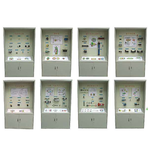


| serial number | name | Checklist | Checklist |
| 1 | Hydraulic pump | gear pump | Working principle of hydraulic pump |
| External gear pump | |||
| Internal gear pump | |||
| vane pump | Single acting vane pump | ||
| plunger pump | Radial piston pump | ||
| Servo variable mechanism | |||
| Axial piston pump | |||
| 2 | Hydraulic motors and hydraulic cylinders | hydraulic motor | Vane hydraulic motor |
| Radial piston motor | |||
| Hydraulic cylinder type | plunger cylinder | ||
| Swing cylinder | |||
| Hydraulic cylinder structure | Piston and piston rod | ||
| buffer device | |||
| Single rod hydraulic cylinder | |||
| 3 | Hydraulic control valve | Directional control valve | Ordinary one-way valve |
| Two-position three-way solenoid valve | |||
| Hydraulic control check valve | |||
| Three-position five-way solenoid valve | |||
| Manual reversing valve | |||
| Two-position four-way solenoid valve | |||
| Motorized reversing valve | |||
| Three-position four-way solenoid valve | |||
| 4 | Hydraulic control valve | pressure control valve | Direct acting relief valve |
| Pilot operated relief valve | |||
| flow control valve | Fixed differential pressure reducing valve | ||
| Fixed ratio pressure reducing valve | |||
| 5 | Hydraulic transmission components | Pipe joint | Pipe joint |
| Quick Connector | |||
| filter | Surface coarse filter | ||
| paper filter | |||
| depth filter | |||
| Accumulator | Level gauge | ||
| silencer | |||
| 6 | Air source, cylinder and *r motor | Air compressor | small *r compressor |
| Compressor accessories | |||
| cylinder | Ordinary cylinder | ||
| Thin film cylinder | |||
| *r motor | Ordinary impact cylinder | ||
| Swing cylinder | |||
| vane motor | |||
| 7 | Pneumatic control valve | Directional control valve | One way control valve |
| Air pressure control directional valve | |||
| pressure control valve | Direct acting solenoid valve | ||
| Pilot solenoid valve | |||
| Direct acting solenoid valve | |||
| Delay reversing valve | |||
| 8 | Pneumatic control valve | flow control valve | Exhaust throttle valve |
| Flexible throttle valve | |||
| Proportional valves and servo valves | OR element | ||
| Double pneumatic control valve | |||
| Single solenoid valve | |||
| Three-position five-way solenoid valve | |||
| pneumatic logic components | Gas triple piece pressure reducing valve | ||
| Non-access control door components | |||
| is the gate and gate component | |||
| or non-element |
 Wechat scan code follow us

24-hour hotline+86 18916464525

Phone18916464525
ADD:Factory 414, District A, No. 6, Chongnan Road, Songjiang Science and Technology Park, Shanghai ICP: Sitemap