DYZT-S2 steel surveying and mapping experimental device
Release time:2024-05-14 20:30viewed:times
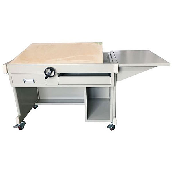
Specifications (L×W×H): 1500×720×800mm
Technical structural parameters:
The overall steel plate frame structure is used: drawing desktop, computer display platform, m*n cabinet, tool drawer and keyboard drawer, etc.;
left and right desktop base materials: left The side m*n desktop adopts the national excellent standard No. 1 (900×600×20mm thick) northeastern basswood thickened drawing board. Special hand-tightened tilt angle adjustment mechanisms for drawing are used on both sides under the desktop to ensure that the desktop is flat and the inclination can be controlled and adjusted synchronously. Adjustment 0-70°. There is a hand-twisting handle on the side, which is convenient and reliable; the support frame on the right side is used as a computer display console, which can be used to place computers, stationery, books, etc.;
3) Multiple storage spaces: lower part of the desktop The left and right sides are equipped with tool drawers and keyboard drawers to meet the needs of d*ly teaching drawing and computer operation; the right side of the desk is equipped with an open m*n cabinet to facilitate the placement of the host computer;
4) Stability adjustment feet: the bottom uses plastic wood horizontal adjustment screws Foot pads or universal wheels are anti-slip, anti-noise, and have adjustment functions to ensure the stability of the desktop and the solid structure.
M*n material specifications and surface treatment:
1) The drawing table bracket is made of high-quality steel rectangular tube material (30×60×1.0mm) and steel plate material above 0.8mm; all table structure or component steel materials are national standard products, and the welding parts must Using carbon dioxide shielded welding process, full welding, the solder joints are firm, smooth and beautiful, without bubbles, burrs, missing welds or false welds, and are wear-resistant and anti-scratch; all are electrostatically sprayed evenly (the color is light gray) , complete degreasing, rust removal, pickling and phosphating treatment should be carried out before spraying to ensure that there will be no peeling off or anti-rust of the sprayed plastic.
2) The desktop base material is a thickened professional drawing board (900×600×20mm thick) of Northeastern basswood that meets the national standards, which is durable and not easily deformed. The computer display auxiliary desktop (600×600×18mm) is made of environmentally friendly E1 grade The melamine desktop board is formed by high-frequency hot pressing in one step. It has strong n*l-holding power, is not easy to expand and deform, and is strong and durable. It is edge-sealed with high-quality PVC of 1.5mm or more and imported hot-melt glue with a fully automatic mechanical edge-banding machine. The edges are neat and smooth and the layer texture is clear.
3) Steel frame student desk configuration (optional) :
(1) 90cm T-square
(2) 90*60cm No. 1 drawing board
(3) Precision drawing instrument (set of 5)
(4) 25cm curve board
(5) 30cm multi-purpose beveled triangle plate
(6) utility knife
(7) triangular scale
(8) multi-function template
(9) large arc template
(10) st*nless steel multi-purpose eraser picture
(11) circle drawing template
(12) drawing pencil (5 pieces) Set)
(13) 81a drawing pen
(14) Student stool (PVC stool surface, steel tube body, liftable) composition drawing stool: plastic steel lifting stool, PVC seat surface, steel tube body, tube body steel thickness 1mm p*nt treatment; stool surface Thickness 6mm, tapered base design; overall height 45cm.
Comprehensive integrated tr*ning virtual simulation system for vocational skills: The model
in the software can be rotated 360°, enlarged, reduced, and translated, and is equipped with universal interactive buttons: return, home page, and help. There are prompts during all virtual simulation tasks, and the software automatically checks the box after completing a task. There are experimental tasks 1 and basic three-dimensional above the tool library. (When the model is rotated, the XYZ space coordinate icon automatically follows the rotation.) A. Plane and three-dimensional: The experimental steps are divided into experimental tasks (text prompt tasks) - building models (drag and drop in the tool library The model is put into the three-projection plane system, and the projection is automatically displayed. There will be a prompt when the selection is wrong) - Change the posture (change by clicking the up, down, left and right arrows) - Select the projection (enter the answer interface, select the three-dimensional projection map completed at this time among the 6 items) ) B. Cutting three-dimensional: The experimental steps are divided into experimental tasks (text prompt tasks) - building the model (drag the model in the tool library into the three-projection plane system, and automatically display the projection) - marking the projection situation (as a three-dimensional projection icon Determine, select the corresponding label symbol in the 14 blank columns) C. Intersecting three-dimensional: The experimental steps are divided into experimental tasks (text prompt tasks) - digging holes (select any digging model, at this time, you will be able to dig holes in the XYZ space coordinates Select any surface, the model will be switched at the same time, and a coordinate slider will appear. According to the displacement of the slider, the model will appear with a corresponding section plane) - aperture change (select 1-4 apertures) - rear through hole - select projection (enter the answer interface) , select the three-dimensional projection image completed at this time among the 8 items) 2. Assembly A, assembly assembly: The experimental steps are divided into experimental tasks (text prompt tasks)-select the assembly model (8 models are optional)-assembly assembly Body (select the tool library model according to the selected model and drag and drop to combine) - Sectioning the combined body (you can select any surface in the XYZ space coordinates, the model is switched at the same time, and a coordinate slider appears. According to the displacement of the slider, the model appears Corresponding section plane)—Select the side projection (enter the answer interface and select the correct side projection among the 3 items based on the known front and horizontal projections) B. Combination picture reading: The experimental steps are divided into experimental tasks (text Prompt task)—Select the combination section view (8 types of pictures are av*lable)—Build the combination model (select the tool library model according to the selected model and drag and drop the combination)—Section the combination (you can select any surface in the XYZ space coordinates, The model is switched at the same time, and a coordinate slider appears. According to the displacement of the slider, the model appears with a corresponding section plane) - Select the left view (enter the answer interface, select the correct left view among the 3 items based on the known m*n view and top view) View) 3. Assembly A, mechanical transmission mechanism : 8 types of mechanisms (worm gear, rack and pinion, screw transmission, out-of-plane meshing gear, in-plane meshing gear, space spur bevel gear, belt drive , ch*n drive) optional , after selecting, the model will appear in the toolbar. Drag and drop the model freely to combine it. After the combination is completed, the model can be operated. Each mechanism comes with an introduction, video demonstration, and drawing method. There are 6 questions in the answering interface, and each question has 4 options.
B. Gear oil pump: Select the tool library model according to the prompts to gradually build the model. You can choose the introduction, drawing method, and animation principle (the internal movement principle of the model is visible) to learn. There are 2 questions in the answering interface, each with 4 options.
C. Mechanical mechanism construction: 2 types of mechanisms (2-DOF robotic arm, 3-DOF robotic arm). Select the tool library model according to the prompts to gradually build the model. After the combination is completed, the model can be operated. Each mechanism comes with an introduction and video demonstration. . There are 2 questions in the question-answering interface (which can only be entered after both models have been built), each with 4 options.


 Wechat scan code follow us
