Shanghai Daiyu Education Equipment Manufacturing Co., Ltd.
Language:


| Lathe bed form | Integrated bed | |
| Maximum workpiece rotation diameter on the bed | ≥320mm | |
| Maximum workpiece length (center distance) | ≥500mm | |
|
Maximum workpiece processing diameter |
bed frame | ≥320mm |
| Drag strip | ≥165mm | |
| Maximum workpiece processing length | ≥450mm | |
| Spindle head form/taper/taper hole | MT5 | |
| Spindle through hole diameter | ≥Φ60mm | |
| Spindle speed (variable frequency stepless) | ≥50~2500/rpm | |
| Spindle power | ≥4KW | |
| Rapid moving speed X/Z axis | ≥6000/8000mm/min | |
| Maximum stroke of carriage X/Z axis | ≥230/480mm | |
| Electric knife holder form and number of installed knives | ≥Vertical 4 stations | |
| Tool bar cross-section size | ≥20×20mm | |
| Positioning accuracy X/Z axis | ≤0.02/0.03mm | |
| Repeat positioning accuracy X/Z axis | ≤0.01/0.016mm | |
| Workpiece processing accuracy | IT6~IT7 | |
| Workpiece surface roughness | Ra1.6 | |
| Top sleeve inner hole taper | ≥ Mohs No. 4 | |
| Maximum movement of top sleeve | ≥100mm | |
| Maximum horizontal movement | ±10mm | |
| Dimensions | ≥2000×1300×1700mm | |
| Machine tool net weight | ≥1400KG | |
| serial number | Material name and specification model | quantity | unit |
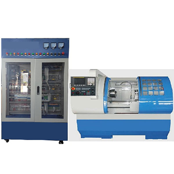
| 1 | CNC system (using FANUC 0I TF) | 1 | tower |
| 2 | Machine tool tr*ning console (made of iron sheet metal spray-plastic structure) | 1 | tower |
| 3 | CK6432 CNC lathe | 1 | tower |
| 4 | Hand pulse generator (FANUC handwheel) (mounted on the panel) | 1 | tower |
| 5 | Four-station tool holder (including wrench) | 1 | set |
| 6 | cooling pump motor | 1 | tower |
| 7 | Three-phase AC servo motor (βIS series) (installed on the physical machine tool) | 2 | tower |
| 8 | AC servo unit (βIS series, installed on the panel) | 2 | tower |
| 9 | X, Z axis positive and negative limits, machine tool zero return switch (installed on the physical machine tool) | 2 | Only |
| 10 | Frequency converter (mounted on panel) | 1 | tower |
| 11 | I/O board (FANUC) | 1 | piece |
| 12 | Splitter (FS-50BB) (mounted on panel) | 1 | piece |
| 13 | Voltmeter 6L2 (0~450V) (mounted on the panel) | 1 | Only |
| 14 | Voltmeter 85L17 (0~450V) (mounted on the panel) | 1 | Only |
| 15 | 24V digital DC voltmeter (mounted on panel) | 2 | Only |
| 16 | Arc extinguisher 31TX1-31A03 (mounted on panel) | 1 | Only |
| 17 | AC contactor CJX1-22 (CHINT) (mounted on the panel) | 4 | Only |
| 18 | DC relay MY2N (mounted on panel) | 6 | Only |
| 19 | KT18-32 (mounted on panel) | 3 | Only |
| 20 | Circuit breaker DZ47-60-C5 (CHINT) (mounted on the panel) | 3 | Only |
| twenty one | Leakage protector DZ47LE-32 (CHINT) (installed on the cabinet) | 1 | Only |
| twenty two | EL (panel mounted) | 1 | Only |
| twenty three | Fan (installed in the cabinet) (installed on the panel) | 1 | Only |
| twenty four | Emergency stop switch (strong current) (installed on the panel) | 1 | Only |
| 25 | Emergency stop switch (drive) (installed on the sub-panel) | 1 | Only |
| 26 | Fan switch (mounted on panel) | 1 | Only |
| 27 | Light switch (panel mounted) | 1 | Only |
| 28 | Power indicator light (installed on the cabinet) | 1 | Only |
| 29 | DC 24V power supply (installed in the cabinet) | 2 | tower |
| 30 | 650W transformer (installed in the cabinet) | 1 | tower |
| 31 | 1500W transformer (installed in the cabinet) | 1 | tower |
| 32 | Keys (2 per set) | 1 | set |
| 33 | CAD/CAM software CD | 1 | open |
| 34 | Inverter User Manual | 1 | Book |
| 35 | FUANC 0I-D User Manual | 1 | Book |
| 36 | FUANC 0I D Service Manual | 1 | Book |
| 37 | FUANC 0I D parameter description | 1 | Book |
| 38 | Tr*ning platform instruction book (including intelligent fault instruction manual) | 1 | Book |
| 39 | CNC lathe fault circuit diagram | 1 | share |
| 40 | Intelligent fault assessment software | 1 | set |
| 41 | RS232 interface transmission line and plug (5 meters) | 1 | set |
| serial number | name | Specification | quantity | Remark |
| 1 | Three jaw chuck | 1 | Already installed on the machine tool | |
| 2 | Chuck positive jaw | 1 p*r | Already installed on the chuck | |
| 3 | Chuck anti-jaw | 1 p*r | random | |
| 4 | Chuck wrench | 1 handful | random | |
| 5 | Tool holder wrench | 1 handful | random | |
| 6 | Machine mattress iron | 6 | random | |
| 7 | dead top | 1 | random | |
| 8 | Knife spacer | 1 box | random | |
| 9 | turning tool | 4 handfuls | random | |
| 10 | T*lstock wrench (dull wrench) | 1 handful | random | |
| 11 | Plastic rod (test piece) | 1 box | random | |
| 12 | screwdriver | cross | 2 handfuls | random |
| 13 | Allen wrench | 1 set | random |
 Wechat scan code follow us

24-hour hotline+86 18916464525

Phone18916464525
ADD:Factory 414, District A, No. 6, Chongnan Road, Songjiang Science and Technology Park, Shanghai ICP: Sitemap