Shanghai Daiyu Education Equipment Manufacturing Co., Ltd.
Language:


| Technical name | Technical Parameters | |
| working desk size | ≥800×320mm | |
| journey | X axis/rapid feed | ≥510mm/15M |
| Y axis/rapid feed | ≥350mm/15M | |
| Z axis/rapid feed | ≥420mm/10M | |
| Spindle maximum speed | ≥8000rpm | |
| handle form | ≥BT40 | |
| Feed rate | 8000mm/min | |
| T-shaped slot width | 14mm | |
| T-slot spacing | 110mm | |
| Distance from spindle end to worktable | 70-470mm | |
| Distance from spindle center to column | 375mm | |
| Maximum load-bearing capacity of workbench | ≥200kg | |
| Minimum setting unit | 0.001mm | |
| Repeatability | ≤±0.0075mm | |
| positioning accuracy | ≤±0.01mm | |
| M*n motor | ≥3.7/5.5KW | |
| Tool magazine type/number | ≥Bamboo hat type BT40/12T | |
| Air pressure | 4-6kgf/cm2 | |
| Machine tool dimensions | ≥2000×1720×2500mm | |
| weight | ≥2600kg | |
| serial number | Name | M*n components, devices and specifications | quantity |
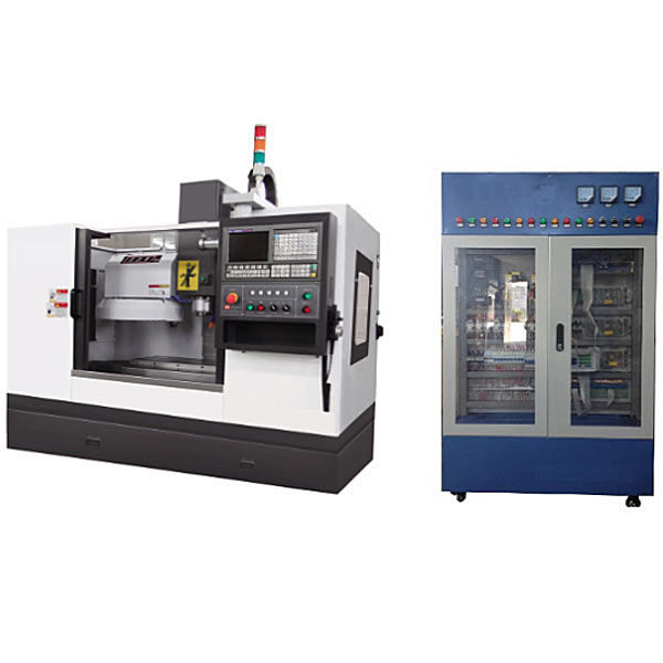
| 1 | Machine tool tr*ning cabinet | 1000mm×600mm×1800mm | 1 set |
| 2 | Machining Center | High speed VML7135A | 1 set |
| 3 | CNC system | FANUC FANUC 0I MF | 1 set |
| 4 | Servo spindle | Fanuc original 3.7/5.5kw motor | 1 set |
| 5 | Servo drive | FANUC original one-piece | 1 set |
| 6 | servo motor | FANUC βis8/3000 | 2 units |
| 7 | Tool magazine form | Hat type 12T | 1 set |
| 8 | Electronic handwheel | Hand operated pulse generator | 1 |
| 9 | Electrical components | Leakage protectors, circuit breakers, AC contactors, relays, sensors , connecting wires, etc. | 1 set |
| 10 | Electrical control circuit diagram | Cont*ns f*lure points | 1 serving |
| 11 | User Manual | FANUC 0I-F | 1 copy |
| 12 | M*ntenance Manual | FANUC 0I-F | 1 copy |
| 13 | Parameter Description | FANUC 0I-F | 1 copy |
 Wechat scan code follow us

24-hour hotline+86 18916464525

Phone18916464525
ADD:Factory 414, District A, No. 6, Chongnan Road, Songjiang Science and Technology Park, Shanghai ICP: Sitemap