Shanghai Daiyu Education Equipment Manufacturing Co., Ltd.
Language:


| serial number | Name | M*n components, devices and specifications | quantity | Remark |
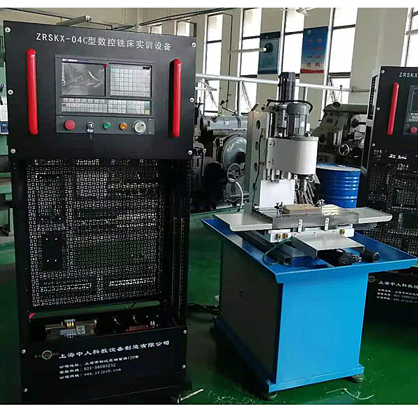
| 1 | Machine tool tr*ning cabinet | 800mm×600mm×1800mm | 1 set | |
| 2 | Precision three-dimensional coordinate system | 800×660×1500mm | 1 set | |
| 3 | console | 1200mm×600mm×780mm | 1 set | |
| 4 | CNC system | HNC-21M3 | 1 set | |
| 5 | Frequency converter | 0.75KW | 1 set | |
| 6 | Servo drive | 15 series | 3 units | |
| 7 | servo motor | 3.2N/M | 3 units | |
| 8 | Electronic handwheel | Hand operated pulse generator | 1 | |
| 9 | Spindle motor | 3B-120W | 1 | |
| 10 | Electrical components | Leakage protectors, circuit breakers, AC contactors, relays, sensors, connecting wires, etc. | 1 set | |
| 11 | computer | M*nstream brand configuration | 1 set | User configured |
| 12 | Profile computer desk | Overall dimensions: 600mm×560mm×1100mm | 1 piece | |
| 13 | Electrical control circuit diagram | Cont*ns f*lure points | 1 serving | |
| 14 | Inverter manual | 1 copy | ||
| 15 | Programming manual | 1 copy | ||
| 16 | Commissioning manual | 1 copy | ||
| 17 | Operation Manual | 1 copy | ||
| 18 | Experiment instructions | 1 copy | ||
| 19 | Intelligent assessment system module | Including software and hardware | 1 set |
| serial number | Material name and specification model | quantity | unit |
| 1 | Wire strippers | 1 | Only |
| 2 | Diagonal pliers | 1 | Only |
| 3 | Crimping Tool | 1 | Bundle |
| 4 | Needle nose pliers | 1 | Bundle |
| 5 | Scissors for civilian use | 1 | Bundle |
| 6 | Cross batch 3*50 6*80 | Each 1 | Bundle |
| 7 | One word batch 3*75 6*80 | Each 1 | Bundle |
| 8 | Test pen neon tube type | 1 | Only |
| 9 | Multimeter VC890B | 1 | Only |
| 10 | Square feet level 0 marble 300*300 | 1 | tower |
| 11 | Leverage dial indicator | 1 | Only |
| 12 | Magnetic watch base | 1 | Only |
| 13 | Rubber hammer | 1 | Bundle |
| 14 | Strip level | 1 | indivual |
| 15 | Fuse 4A | 20 | Only |
| 16 | Travel switch (matching) | 4 | Only |
 Wechat scan code follow us

24-hour hotline+86 18916464525

Phone18916464525
ADD:Factory 414, District A, No. 6, Chongnan Road, Songjiang Science and Technology Park, Shanghai ICP: Sitemap