Shanghai Daiyu Education Equipment Manufacturing Co., Ltd.
Language:


1. Power supply AC 220V 50HZ
2. DC power supply: input AC 220V, output DC 24V/2A
3. Oil-free silent *r compressor: working power supply: AC220V; motor power: 780W nominal capacity 30L;
rated output *r pressure 0.8Mpa, noise: 58 decibels
4. Dimensions of the tr*ning device: 1500mm × 650mm × 1700mm
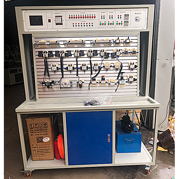
2. M*n features
1. It is m*nly composed of tr*ning tables, tr*ning tables , pneumatic components and electrical control devices.
2. The tr*ning table and tr*ning platform are made of iron with a double-layer matt dense pattern spray-plastic structure. The tr*ning table drawers store hydraulic components, etc.
3. It is equipped with commonly used pneumatic components for industrial use, and is equipped with a transition base plate, so that the components can be conveniently and freely inserted on the tr*ning table panel (the panel has an aluminum alloy profile structure in the form of a "T" groove). The loop overlap adopts quick-change connectors, which are convenient and quick to disassemble and connect.
4. The pressure of the practical tr*ning *r source is low, and the electrical control adopts low-voltage DC 24V power supply; the practical tr*ning *r path and control circuit are safe and reliable, and are equipped with manual, automatic, sequential and other control functions.
5. The tr*ning control unit uses an independent relay control unit for electrical control.
6. Hydraulic and pneumatic transmission design and control virtual simulation software
3. Basic pneumatic tr*ning circuit
1. Single-acting cylinder reversing circuit
2. Double-acting cylinder reversing circuit
3. Single-acting cylinder speed control circuit 4.
Double-acting cylinder one-way speed regulating circuit
5. Double-acting cylinder two-way regulating circuit Speed circuit
6, speed switching circuit
7, buffer circuit
8, secondary pressure control circuit
9, high and low pressure conversion circuit 10
, counting circuit
11, delay circuit 12
, overload protection circuit
13, interlock circuit
14, single cylinder single reciprocation Control loop
15, single cylinder continuous reciprocating action loop
16, linear cylinder, rotating cylinder sequential action loop
17, multi-cylinder sequential action loop
18, double cylinder, synchronous action loop
19, return cylinder linkage loop
20, unloading loop
21, OR gate Type shuttle valve application circuit
22. Quick exhaust valve application circuit
4. Configuration list
| serial number | name | model | quantity | Remark |
| 1 | Tr*ning table | 1 piece | ||
| 2 | Tr*ning platform | 1 set | ||
| 3 | Power module | 1 piece | ||
| 4 | Relay control module | 1 piece | ||
| 5 | Oil-free silent *r compressor | 1 set | ||
| 6 | single acting cylinder | QGX25ⅹ100 | 1 | |
| 7 | Double acting cylinder | QGX25ⅹ100 | 2 | |
| 8 | Rotating cylinder | 1 | ||
| 9 | triple piece | AC2000 | 1 | |
| 10 | Pressure reducing valve (with pressure gauge) | AR2000 | 1 | |
| 11 | Manual reversing valve | H210—08 | 1 | |
| 12 | Single solenoid directional valve (two-position three-way) | 3V210-8 | 1 | |
| 13 | Single solenoid directional valve (two-position five-way) | 4V210-8 | 2 | |
| 14 | Double solenoid directional valve (two-position five-way) | 4V220-8 | 1 | |
| 15 | Double solenoid directional valve (three-position five-way) | 4V230-8 | 1 | |
| 16 | Single gas directional valve (two-position five-way) | 4A210—08 | 2 | |
| 17 | Two-gas directional valve (two-position five-way) | 4A210—08 | 2 | |
| 18 | Stroke valve (machine control) | MOV-2 | 1 | |
| 19 | Stroke valve (button) | MOV-3A | 1 | |
| 20 | Stroke valve (button with lock) | MOV-3A | 1 | |
| twenty one | Or gate type shuttle valve | ST-02 | 2 | |
| twenty two | Double pressure valve | |||
| twenty three | Quick exhaust valve | QE—02 | 2 | |
| twenty four | One-way throttle valve | ASC-08 | 2 | |
| 25 | One-way throttle valve (mounted on the cylinder block) | JSC601 | 7 | |
| 26 | One-way valve | 1/4 | 2 | |
| 27 | sequence valve | 1 | ||
| 28 | Calmness | 1 | ||
| 29 | silencer | 1/8 | 2 | |
| 30 | silencer | 1/4 | 1 | |
| 31 | Tee (T-shaped tee) | Ø6 | 4 | |
| 32 | Tee (Y-shaped reducing tee) | Ø8—Ø6 | 1 | |
| 33 | four links | Ø6 | 2 | |
| 34 | trachea | PU6ⅹ4 | 20 meters | |
| 35 | Stroke switch (mounted on the cylinder) | 2 | ||
| 36 | Allen wrench | 3 handfuls | ||
| 37 | screwdriver | 2 handfuls | ||
| 38 | Scissors | 1 handful | ||
| 39 | adjustable wrench | 1 handful | ||
| 40 | Needle nose pliers | 1 handful | ||
| 41 | raw material belt | 1 | ||
| 42 | Air hole plug | Ø6 | 10 pieces | |
| 43 | Pneumatic tr*ning instructions | 1 volume |
 Wechat scan code follow us

24-hour hotline+86 18916464525

Phone18916464525
ADD:Factory 414, District A, No. 6, Chongnan Road, Songjiang Science and Technology Park, Shanghai ICP: Sitemap