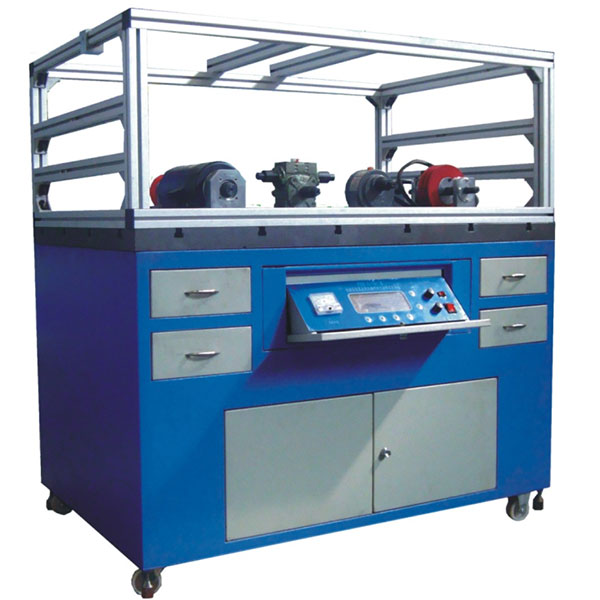
DYJX-PSY mechanical system integration and parameter visual analysis training device
Release time:2024-05-10 10:27viewed:times
1. M*n features 1. Can design and assemble more than 40 types of mechanical
transmission systems for space and plane installation ; 2. Modular design of transmission parts for easy installation; 3. The transmission parts library is complete in variety, allowing students to have a comprehensive understanding of transmission forms. ; 4. The detection and analysis software can be used to detect and analyze the transmission parameters of the mechanical system in real time, and analyze the performance, installation status, and operating conditions of the system from their changing patterns, and adjust the system design and installation accordingly; 5. Teaching The software provides students with experimental background instructions and experimental bench introductions, and has multimedia teaching functions; 6. An open platform that can use analysis software, and users can process their own data; 7. Modular design, providing plane and space assembly platforms, with Various component libraries and various system combination solutions inspire students' innovative thinking. 8. It is equipped with force measurement, angular and linear position sensors and a special detection system, which can test the relevant parameters of the mechanical system; it is equipped with comprehensive software (including mechanical system parameters and efficiency measurement and visual design key points, background database, etc. 9. The product provides convenient experimental innovative equipment for teaching and researching mechanical design in colleges and universities; 2. M*n experimental content 1. Design and assembly of mechanical transmission system; the experimental bench provides flat and spatial installation, and the flat and flat surfaces can be designed as needed. One-stage and multi-stage transmission systems in space. 2. Mechanical system integrated design and assembly (including actuators) The experimental bench is equipped with actuators with various load and motion characteristics, and the mechanical integrated system can be designed accordingly. Virtual design The experimental bench provides virtual software to simulate the design and assembly of mechanical systems. 4. Mechanical system efficiency detection; the experimental bench is equipped with a set of efficiency detection sensors and detection systems for the mechanical transmission system, which can detect the system efficiency. 5. Mechanical transmission. Component performance testing and actuator motion detection and analysis; the experimental bench provides a motion detection system for detecting rotating and linear motion components. 3. M*n technical parameters: 1. DC motor power: 0.6KW; synchronous speed 1500r/min 2. Magnetic powder brake. Loading range: 0~25N*m; 3. Motor speed regulator: 1 set Speed regulation range: 0-1500rpm, 4. Angular displacement sensor: voltage/pulse number 5V/360P 2 pieces; 5V/1000P 1 piece; 5. Linear displacement sensor: 200mm Voltage: DC5V Accuracy: 0.05 6. Pressure sensor: 1 piece for 5kg; 1 piece for 25kg; accuracy 0.05; 7. Microcomputer test system: The test system includes a computer, monitor, and test analysis software (data processing, real-time curve Drawing, automatic printing of report curves, saving functions, etc.); 8. Maximum installation center height: 130mm; 9. Overall dimensions: 1200mm*800mm*1600mm; 10. Weight: 480kg; 11. Virtual simulation teaching system mechanical tr*ning safety education virtual Simulation software: This software is developed based on unity3d. The software adopts the form of three-dimensional roaming. Movement can be controlled by the keyboard and the lens direction can be controlled by the mouse. It is equipped with mechanical safety distance experiments, mechanical safety protection device experiments, and basic assessment of mechanical safety protection design. During the experiment The three-dimensional roaming screen uses arrows and footprints to prompt you to move to the experimental location. The circle around the mechanical object shows the working radius. The experimental process is accompanied by a dialog box for the three-dimensional robot to remind you. A. The mechanical safety distance experiment content includes preventing the upper and lower limbs from touching the danger zone. Safety distance experiment (divided into two types of fence heights and opening sizes). After selecting to enter, the requirements of GB23821-2009 "Safe Distance for Mechanical Safety to Prevent Upper and Lower Limbs from Touching Danger Zones" pop up in front of the camera. Error demonstration: The experimental process is when the human body enters the mechanical object. After the working radius is damaged, the blood-colored picture and voice prompts that the user has received mechanical damage and returned to the original position to conduct the next experiment. The last step is the correct approach. B. Mechanical safety protection device experiments are divided into safety interlock switches, safety light curt*ns, safety mats, safety laser scanners and other protection device experiments. Optional categories (safety input, safety control, safety output, others), manufacturers, products List (safety interlock switch, safety light curt*n, safety mat, safety laser scanner, safety controller, safety relay, safety guardr*l). There is a blue flashing frame reminder at the installation location. Experimental process: select the safety guardr*l and install it, select the safety interlock switch (or select the safety light curt*n, safety mat, safety laser scanner) and install it, select the safety controller and install it in the electrical control box , select the safety relay and install it in the electrical control box, click the start button on the electrical control box. If you enter a dangerous area, the system will sound an alarm and the mechanical object will stop working. Select the reset button on the electrical control box to stop. C. The basic assessment of mechanical safety protection design requires the completion of the installation of the mechanical safety system, and the correct installation of safety guardr*ls, safety interlock switches, safety light curt*ns, safety mats, safety laser scanners, safety controllers, safety relays, 24V power supplies, signal lights and Emergency stop button. The assessment is divided into ten assessment points. Some assessment points have 3 options, which are freely chosen by the students. After selecting the final 10 assessment points, submit for confirmation, and the system will automatically obt*n the total score and the score of each assessment point. . D. The software must be on the same platform as a whole and must not be displayed as separate resources. E. At the same time, we provide customers with the VR installation package of this software to facilitate users to expand into VR experiments. VR equipment and software installation and debugging are not required. Mechanical Assembly and Fitter
Assembly virtual simulation software: This software is developed based on unity3d, with optional 6-level image quality. It is equipped with design and virtual disassembly and assembly of reducers and shafting structures, design and simulation of common mechanical mechanisms, mechanism resource library, typical mechanical mechanisms (gasoline engines) virtual disassembly), the software is a whole software and cannot be individual resources.
A. Reducer design and virtual disassembly interface can choose worm gear bevel gear reducer, two-stage expanded cylindrical gear reducer, bevel cylindrical gear reducer, coaxial cylindrical gear reducer, bevel gear reducer, and one-stage cylindrical gear reducer. Gear reducer.
Worm bevel gear reducer: After entering the software, the assembly content is automatically played. Each step in the video has a text description
. Secondary expandable cylindrical gear reducer: After entering the software, the content is played in the form of a video. The video content should include: Part name ( Scan the QR code to see the names of parts), disassembly and assembly demonstration (including disassembly and assembly), virtual disassembly (including overall, low-speed shaft, medium-speed shaft, high-speed shaft, box cover, box seat)
conical cylindrical gear reducer, Coaxial cylindrical gear reducer, bevel gear reducer, first-level cylindrical gear reducer: click to enter and automatically jump to the edrawings interface. The models are all three-dimensional models. By clicking on the parts, the names of the parts are displayed, and the 360° view is av*lable Rotate, zoom in, zoom out, pan, and move parts to disassemble and assemble the entire reducer. At the same time, you can select the home button to return to the original state of the reducer. The bevel gear reducer and the first-stage cylindrical gear reducer have added the function of inserting a cross section, and the cross section can be freely dragged to observe the internal structure of the reducer.
B. Shaft structure design and virtual disassembly and assembly interface optional parts recognition, disassembly and assembly demonstration, and actual operation.
1. Parts recognition: three-dimensional model and part name including helical gear, non-hole end cover, coupling, coupling key, shaft, gear key, hole end cover, shaft sleeve, deep groove ball bearing, any All parts can be rotated 360°
2. Disassembly and assembly demonstration: There are 2 built-in cases. When you move the mouse to the position of a cert*n part (except the base and bearing seat), the part will automatically enlarge and the name of the part will be displayed. It is equipped with disassembly and Assembly button, the function is to automatically complete the disassembly and assembly of the shaft system structure by the software. All three-dimensional scenes can be rotated, enlarged, reduced and translated 360° in all directions.
3. Practical operation: The three-dimensional parts are neatly placed on the table. Students manually select the corresponding parts and move them to the shaft system structure. The parts can be installed only when they are placed in the correct order and in the correct position. There is a restart button to facilitate students to restart. Conduct virtual experiments. When you move the mouse to a cert*n part location (except the base and bearing seat), the part will automatically enlarge and the part name will be displayed.
C. Common mechanical mechanism design and simulation, optional hinge four-bar mechanism design and analysis, I\II type crank rocker mechanism design and analysis, offset crank slider mechanism design and analysis, crank swing guide rod mechanism design and analysis, hinge Four-bar mechanism with integrated trajectory, eccentric linear-acting roller push rod cam , and centering linear-acting flat-bottomed push rod cam.
1. Each mechanism should be able to input corresponding parameters, and the software can automatically calculate the parameters, and can perform motion simulation and automatically draw curves.
D. The mechanism resource library includes 11 types of planar link mechanisms, 5 types of cam mechanisms, 6 types of gear mechanisms, 8 types of transmission mechanisms, 11 types of tightening mechanisms, 6 types of gear tr*n mechanisms, and 8 types of other mechanisms (mechanical equipment simulation)
E , virtual disassembly and assembly of gasoline engines, optional crankcase assembly and disassembly demonstration, crankcase virtual assembly, valve tr*n assembly and disassembly demonstration, valve tr*n virtual assembly
1. Crankcase assembly and disassembly demonstration and valve tr*n assembly and disassembly demonstration both have disassembly button, assembly button, restart, and decomposition observation button. When the mouse is moved to a cert*n part position, the part will automatically enlarge and the part name will be displayed. The software automatically completes the disassembly and assembly of the shaft system structure. When using the decomposition observation button, the 3D model of the crankcase or gas distribution system automatically displays an exploded view, which can be rotated, enlarged, reduced, and translated 360°.
2. The 3D parts of the crankcase virtual assembly and the gas distribution system virtual assembly are neatly arranged When placed on the desktop, students manually select the corresponding parts and move them to the mechanism. The parts can be installed only when they are placed in the correct order and in the correct position. There is a restart button to facilitate students to re-perform the virtual experiment. When you move the mouse to cert*n part locations, the part names are automatically displayed.


 Wechat scan code follow us
