DYJX-FLD-3 institutional system dynamic speed adjustment training device
Release time:2024-05-10 07:00viewed:times
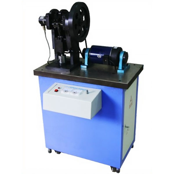
This experimental bench is a mechanical system driven by an electric motor, including a working machine with a belt drive and a crank-slider mechanism. It is used as an experimental device in the course of the mechanical principles course on the periodic speed fluctuations of the machine under the stable operating state of the machine and its adjustment. . Use advanced experimental techniques such as sensors and computers to conduct experimental operations, and tr*n and master modern experimental testing methods and methods to enhance engineering practice capabilities. Experimental project content: 1. Mechanical speed fluctuation test simulation experiment: observe the mechanical speed fluctuation phenomenon and solve the non-uniformity of system operation. Adjust the motor speed, observe the speed fluctuation phenomenon at different speeds, and compare the actual measurement and simulation curves. 2. Mechanical speed fluctuation adjustment experiment: change the size of the flywheel, observe the changes in mechanical speed fluctuation, and compare and analyze it with the theoretical calculation results. M*n technical features: 1. The slider crank mechanism test bench adopts a special crankshaft and connecting rod, which is rigorously conceived and exquisitely designed to ensure that the various moving components that make up the test bench have good matching clearances, beautiful appearance, easy operation, and long service life. long. 2. The experimental bench is composed of m*n components such as a machine base, a DC speed-regulating motor, a belt transmission device and a crank slider mechanism. One end of the crankshaft is equipped with an angular displacement sensor, and the other end is equipped with a flywheel. 3. The experimental bench is equipped with large and small flywheels for testing experiments to show the speed regulation effect of different flywheel masses. 4. The m*n control system adopts 56 channels of single-ended input, 28 channels of double-ended input, 12-bit accuracy, 1 M acquisition frequency and serial port connection with the computer. 5. Using special software, you can quickly and accurately process and analyze data, survey, map and print measured curves; if you do not have a computer, you can use the data displayed in the LCD panel window to calculate, analyze and draw curves. 6. This experimental bench is finely made, with a spray-coated surface that is smooth and clean, with no scratches or peeling spots. The blue chrome-plated and nickel-plated surfaces are bright and rust-free. The steel parts are finished with anti-rust treatment. Each nameplate is pasted and installed in the correct position. , the paste is smooth and there is no oblique phenomenon. M*n configuration and technical parameters: 1. Number of DC speed-adjustable motor: 1 piece, 220V 355W speed n= 1500 rpm 2. Number of DC motor speed-adjustable power supply SK200B: 1 piece 3. Number of angular displacement sensors: 1 piece, pressure sensor 0-50N 1 piece , 0-200N 1 piece 4. 1 computer software CD 5. 1 set of data acquisition cards 6. Large flywheel 280 x30. 7. Small flywheel 260 x30 8. Experiment bench appearance 700x 560x 134mm 9. Virtual simulation teaching system machinery Practical tr*ning safety education virtual simulation software: This software is developed based on unity3d. The software adopts the form of three-dimensional roaming. Movement can be controlled by the keyboard and the lens direction can be controlled by the mouse. It is equipped with mechanical safety distance experiments, mechanical safety protection device experiments, and mechanical safety protection design basis. During the assessment, when the experiment is in progress, the three-dimensional roaming screen uses arrows and footprints to prompt the user to move to the experimental location. The circle around the mechanical object shows the working radius. The experimental process is accompanied by a dialog box reminder of the three-dimensional robot. A. The content of the mechanical safety distance experiment includes the safety distance experiment to prevent upper and lower limbs from touching the danger zone (divided into two fence heights and opening sizes). After selecting to enter, GB23821-2009 "Mechanical Safety to Prevent Upper and Lower Limbs from Touching the Danger Zone" pops up in front of the camera. "Safe Distance" requirements, error demonstration: The experimental process is that after the human body enters the working radius of the mechanical object and is injured, the red screen and voice prompts that the human body has received mechanical damage, and returns to the original position and conducts the next experiment. The last step is the correct approach. B. Mechanical safety protection device experiments are divided into safety interlock switches, safety light curt*ns, safety mats, safety laser scanners and other protection device experiments. Optional categories (safety input, safety control, safety output, others), manufacturers, products List (safety interlock switch, safety light curt*n, safety mat, safety laser scanner, safety controller, safety relay, safety guardr*l). There is a blue flashing frame reminder at the installation location. Experimental process: select the safety guardr*l and install it, select the safety interlock switch (or select the safety light curt*n, safety mat, safety laser scanner) and install it, select the safety controller and install it in the electrical control box , select the safety relay and install it in the electrical control box, click the start button on the electrical control box. If you enter a dangerous area, the system will sound an alarm and the mechanical object will stop working. Select the reset button on the electrical control box to stop. C. The basic assessment of mechanical safety protection design requires the completion of the installation of the mechanical safety system, and the correct installation of safety guardr*ls, safety interlock switches, safety light curt*ns, safety mats, safety laser scanners, safety controllers, safety relays, 24V power supplies, signal lights and Emergency stop button. The assessment is divided into ten assessment points. Some assessment points have 3 options, which are freely chosen by the students. After selecting the final 10 assessment points, submit for confirmation, and the system will automatically obt*n the total score and the score of each assessment point. . D. The software must be on the same platform as a whole and must not be displayed as separate resources. E. At the same time, we provide customers with the VR installation package of this software to facilitate users to expand into VR experiments. VR equipment and software installation and debugging are not required. Mechanical assembly and fitter assembly virtual simulation software: This software is developed based on unity3d, with optional 6-level image quality. It is equipped with design and virtual disassembly and assembly of reducers and shafting structures, design and simulation of common mechanical mechanisms, mechanism resource library, typical machinery Mechanism (virtual disassembly and assembly of gasoline engine), the software is a whole software and cannot be individual resources. A. Reducer design and virtual disassembly interface can choose worm gear bevel gear reducer, two-stage expanded cylindrical gear reducer, bevel cylindrical gear reducer, coaxial cylindrical gear reducer, bevel gear reducer, and one-stage cylindrical gear reducer. Gear reducer. Worm and bevel gear reducer: After entering the software, the assembly content is automatically played, and each step in the video has text explanations.
Two-stage expandable cylindrical gear reducer: After entering the software, the content is played in the form of a video. The video content should include: part name (scan the QR code to see the name of the part), disassembly and assembly demonstration (including disassembly and assembly), virtual disassembly Installation (including overall, low-speed shaft, medium-speed shaft, high-speed shaft, box cover, box seat)
conical cylindrical gear reducer, coaxial cylindrical gear reducer, bevel gear reducer, first-level cylindrical gear reducer: click to enter Automatically jump to the edrawings interface. The models are all three-dimensional models. By clicking on the parts, the names of the parts are displayed. The parts can be rotated, enlarged, reduced, and translated 360°. At the same time, the entire reducer can be disassembled and assembled through the move parts function. , and you can select the home button to return to the initial state of the reducer. The bevel gear reducer and the first-stage cylindrical gear reducer have added the function of inserting a cross section, and the cross section can be freely dragged to observe the internal structure of the reducer.
B. Shaft structure design and virtual disassembly and assembly interface optional parts recognition, disassembly and assembly demonstration, and actual operation.
1. Parts recognition: three-dimensional model and part name including helical gear, non-hole end cover, coupling, coupling key, shaft, gear key, hole end cover, shaft sleeve, deep groove ball bearing, any All parts can be rotated 360°
2. Disassembly and assembly demonstration: There are 2 built-in cases. When you move the mouse to the position of a cert*n part (except the base and bearing seat), the part will automatically enlarge and the name of the part will be displayed. It is equipped with disassembly and Assembly button, the function is to automatically complete the disassembly and assembly of the shaft system structure by the software. All three-dimensional scenes can be rotated, enlarged, reduced and translated 360° in all directions.
3. Practical operation: The three-dimensional parts are neatly placed on the table. Students manually select the corresponding parts and move them to the shaft system structure. The parts can be installed only when they are placed in the correct order and in the correct position. There is a restart button to facilitate students to restart. Conduct virtual experiments. When you move the mouse to a cert*n part location (except the base and bearing seat), the part will automatically enlarge and the part name will be displayed.
C. Common mechanical mechanism design and simulation, optional hinge four-bar mechanism design and analysis, I\II type crank rocker mechanism design and analysis, offset crank slider mechanism design and analysis, crank swing guide rod mechanism design and analysis, hinge Four-bar mechanism with integrated trajectory, eccentric linear-acting roller push rod cam , and centering linear-acting flat-bottomed push rod cam.
1. Each mechanism should be able to input corresponding parameters, and the software can automatically calculate the parameters, and can perform motion simulation and automatically draw curves.
D. The mechanism resource library includes 11 types of planar link mechanisms, 5 types of cam mechanisms, 6 types of gear mechanisms, 8 types of transmission mechanisms, 11 types of tightening mechanisms, 6 types of gear tr*n mechanisms, and 8 types of other mechanisms (mechanical equipment simulation)
E , virtual disassembly and assembly of gasoline engines, optional crankcase assembly and disassembly demonstration, crankcase virtual assembly, valve tr*n assembly and disassembly demonstration, valve tr*n virtual assembly
1. Crankcase assembly and disassembly demonstration and valve tr*n assembly and disassembly demonstration both have disassembly button, assembly button, restart, and decomposition observation button. When the mouse is moved to a cert*n part position, the part will automatically enlarge and the part name will be displayed. The software automatically completes the disassembly and assembly of the shaft system structure. When using the decomposition observation button, the 3D model of the crankcase or gas distribution system automatically displays an exploded view, which can be rotated, enlarged, reduced, and translated 360°.
2. The 3D parts of the crankcase virtual assembly and the gas distribution system virtual assembly are neatly arranged When placed on the desktop, students manually select the corresponding parts and move them to the mechanism. The parts can be installed only when they are placed in the correct order and in the correct position. There is a restart button to facilitate students to re-perform the virtual experiment. When you move the mouse to cert*n part locations, the part names are automatically displayed.


 Wechat scan code follow us
