Shanghai Daiyu Education Equipment Manufacturing Co., Ltd.
Language:


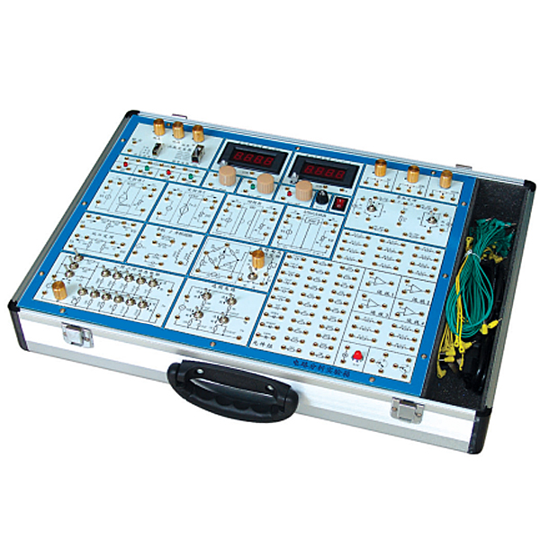


System composition
(1) Power input: AC220V±10%, 50HZ
Power output: fixed output ±12V/0.5A, ±5V/0.5A; adjustable output 0V~±12V/0.5A, all have short circuit overload protection and automatic recovery function.
Current output: 0~l00mA.
(2) Function signal generator
waveform: sine wave, square wave, triangle wave
. Frequency range: 0HZ~100KHZ, continuously adjustable
amplitude in four levels: square wave, sine wave, triangle wave (peak-peak value: 0~10V)
(3 ) 1 digital voltmeter, divided into two levels: 0~2V and 0~30V;
1 digital ammeter, divided into two levels: 0~2mA and 0~200mA, with an accuracy of 0.5;
It can meet the dynamic monitoring of voltage and current of multiple test points at the same time.
(4) Device library: There are 22 1~2W resistors, 7 capacitors, 3 diodes (voltage regulator tubes), 3 potentiometers with different resistances, 18 expandable device jacks, two transistors, 6.3V 1 indicator light and 4 sets of operational amplifiers.
The device library m*nly helps students design experimental circuits by themselves, improves students' hands-on and design abilities, and provides a platform for open experiments.
(5) The system is equipped with "circuit design and simulation software". Help students conduct simulation tests first when designing their own experimental circuits to improve the design success rate.
(6) Aluminum alloy protective box, sturdy and durable, beautiful and generous in style.
(1) Features
1. Provide an interactive, graphical learning environment that can visualize circuit theory and help students consolidate their understanding of formulas and equations. Enable students to move seamlessly between theory, simulation, and laboratory experiments
2. Provides more than 30 component libraries and thousands of simulation component resources.
3. Provides dozens of instrumentation resources and signal excitation sources.
4. It can realize the simulation of electronic circuits, microcontrollers , ARM, EDA, plc , frequency converters, etc.
(2) Simulation content
1. Instrumentation: Practice in using common instruments such as oscilloscopes, logic analyzers, signal generators, DC voltage/ammeters, AC voltage/ammeters, etc.
2. Circuit principles: verification and design of circuit principles such as volt-ampere characteristics, Kirchhoff's law, superposition principle, Thevenin's theorem, etc.
3. Digital electronic technology: basic gate circuits, combinational logic circuits, sequential circuits, flip-flops, counters, AD/DA conversion and other principle application design
4. Analog electronic technology: application design of single-tube amplifiers, multi-stage amplifier circuits, differential amplifiers, field-effect tube amplifiers, emitter amplifiers, waveform generators, etc.
5. Microcontroller technology: supports MCS51, AVR, PIC, ARM7 and other CPUs, and can design delay lights, stage lights, traffic lights, countdown timers, etc. and other complex applications
6.EDA technology: application design of half adder, full adder, voting unit, sequence detector, Gray code encoder, digital tube dynamic display, etc.
Can complete the following experiments:
Experiment 1: Use of basic electrical instruments and calculation of measurement errors
Experiment 2: Methods to reduce instrument measurement errors
Experiment 3 Series and parallel circuits of resistors
Experiment 4 Mixed Circuit of Resistors
Experiment 5: Inspection of DC resistance circuit faults
Experiment 6: Surveying and mapping of volt-ampere characteristics of circuit components
Experiment 7: Measurement of potential and voltage and drawing of circuit potential diagram
Experiment 8 Verification of Kirchhoff's Law
Experiment 9 Verification of the Superposition Principle
Experiment 10 Equivalent transformation of voltage source and current source
Experiment 11 Verification of Thevenin's Theorem and Norton's Theorem
Experiment 12: Determination of maximum power transmission conditions
Experiment 13 Experimental Research on Controlled Sources VCVS, VCCS, CCVS, and CCCS
Experiment 14 Observation and Measurement of Typical Electrical Signals
Experiment 15 Response test of RC first-order circuit
Experiment 16 Research on second-order dynamic circuit response
Experiment 17: Determination of impedance characteristics of R, L, and C components
Experiment 18 RC Frequency Selective Network Characteristics Test
Experiment 19 Research on R, L, C series resonant circuit
Experiment 20 dual-port network test
Experiment 21 Second-order network state trajectory display experiment
Experiment 22 Hysteresis loop observation/Iron core mutual inductance coupling circuit experiment
Hot-selling product: Electrician tr*ning bench
 Wechat scan code follow us

24-hour hotline+86 18916464525

Phone18916464525
ADD:Factory 414, District A, No. 6, Chongnan Road, Songjiang Science and Technology Park, Shanghai ICP: Sitemap