Shanghai Daiyu Education Equipment Manufacturing Co., Ltd.
Language:


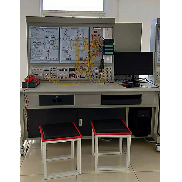


1. The tr*ning platform integrates plc , simulation tr*ning objects, simulation software, and configuration software. Suitable for PLC programmable control practical tr*ning teaching and technician skills appr*sal assessment
2. Each tr*ning device is composed of a control panel, a tr*ning table, a PLC host component, a communication module, a tr*ning module, etc.
3. It adopts a pendant structure and has units such as switching quantities, analog quantities, control objects, and bus communication, which can complete control tr*ning and teaching of logic, simulation, process, motion, etc.
4. The device is equipped with voltage-type and current-type leakage protectors. Each power output has monitoring and short-circuit protection functions. Each measuring instrument has reliable protection functions, making it safe and reliable to use. At the same time, the control panel is also equipped with a timer and Alarm recorder, records the tr*ning and assessment time and the number of misoperations.
5. Safety protection: It has leakage voltage and leakage current protection devices, and is safe and in line with national standards.
(2) Technical requirements
1. Control screen
1.1. AC power control unit
The input power supply is a three-phase five-wire system (~380V±10% 50Hz). The AC power supply supplies power to the device after passing through the *r switch. The grid voltmeter monitors the grid voltage and is protected by an illuminated fuse. The power supply of the control panel is controlled by a key switch and start/stop. Switch control, and also has leakage alarm indication and alarm reset. Provides one set of three-phase five-wire 380V and single-phase 220V power supplies. The output is controlled by a start-stop switch and is protected by a fuse.
1.2. Timer and alarm recorder
The timer and alarm recorder is usually used as a clock and has functions such as setting time, timing alarms, cutting off power, etc. It can also automatically record the number of leakage alarms caused by wiring or operation errors.
1.3. DC power supply, DC voltage/ammeter, logic level output and indication, etc.
DC voltage: 0~15V adjustable output; DC current: 0~20mA adjustable output; DC digital voltmeter/ammeter: voltmeter range 0~200V, input impedance 10MΩ, accuracy 0.5, ammeter range 0~200mA, accuracy Level 0.5; also equipped with logic level output (jog, self-locking), logic level indication, LED digital tube, direction indicator, music box, DC 24V relay, and several signal conversion sockets.
2. Tr*ning table
The tr*ning table is made of iron with a double-layer matt dense spray-p*nted structure. The tabletop is made of fireproof, waterproof, and wear-resistant high-density board. It is equipped with a lockable drawer for placing tools and materials, and a storage cabinet below for placing modules and experiments. The wire and computer desk are combined in a beautiful and elegant shape.
3. Host tr*ning hanging box component: (SIMATIC S7-300)
CPU314-2DP, 24VDC power supply with PROFIBUS-DP master-slave interface; including PROFIBUS-DP network communication; supporting PC/PPI programming cable.
4. Related software
5.1. Programming application software
The operating system and commonly used office software should be installed on the desktop computer; and industrial control software such as Step7, Wincc, Wincc flecxible, etc. should be installed.
5.2. A set of industrial control configuration software:
Open the software programming environment, and you can edit configuration bar diagrams with intuitive and dynamic images and good digital effects for any practical tr*ning, and conduct dynamic tracking and teaching of practical tr*ning
5.3, virtual simulation system
1. M*ntenance of electricians , electronic motors and vocational qualification tr*ning assessment simulation software
This software is in apk format and can be used on PC or mobile. This software can set faults manually or automatically. This software can manually set fault points through the green box in the circuit diagram (you can set up to 39 fault points), you can also automatically set one random fault point, two random fault points, three random fault points, four random fault points, and five random fault points through the system. It has functions such as toolbox, component library, magnifying glass, circuit diagram, etc. You can choose a multimeter for testing through the toolbox, select appropriate components through the component library, and clearly understand each component and circuit through the magnifying glass. This software allows students to understand the working principle and circuit structure of the motor star-delta start control circuit through the setting of faults in the motor star-delta start control circuit and various investigations.
2. Virtual spectrum analyzer, logic analyzer, oscilloscope, and three-meter simulation software:
This software is in apk format and can be used on PC or mobile terminals. The functions of this software are: resistance measurement, AC voltage measurement (measuring transformer, if the multimeter burns out when measuring the transformer, black smoke will emit prompts and can reset the multimeter), determine the polarity of the transistor, measure the DC voltage (the light turns on when the ammeter is turned on), measure the DC current, and determine the quality of the capacitor. This software can drag the red and black pen tips at will. When the two pen tips are dragged and positioned on the object to be measured, a red circle will be displayed. If the positioning is not accurate, no red circle will be displayed, and when incorrect operations are performed (such as the wrong range selected, If the measured data is wrong, etc.), the meter pointer will be unresponsive, prompting errors and re-measurement, etc. This multimeter can select AC voltage range, DC voltage range, resistance range, current range, resistance adjustment to 0, and can enlarge the display data. Clearly view the measured data size. Students can learn the correct use of multimeters through this software.
3. Microcontroller , PLC programmable design and control virtual simulation software:
This software is developed based on unity3d and has built-in experimental steps, experimental instructions, circuit diagrams, component lists, connection lines, power on, circuit diagrams, scene reset, return and other buttons. After the connections and codes are correct, you can start/stop, The forward movement and reverse movement buttons operate the 3D machine tool model to move. In the connected line state, the 3D machine tool model can be enlarged/reduced and translated.
1. Relay control: Read the experiment instructions and enter the experiment. By reading the circuit diagram, select the relays, thermal relays, switches and other components in the component list and drag and drop them into the electrical cabinet. The limiters are placed in the three-dimensional On the machine tool model, you can choose to cover it, and some component names can be renamed. Then click the Connect Line button to connect terminals to terminals. After successfully connecting the machine tool circuit, choose to turn on the power and proceed. If the component or line An error box will pop up if there is a connection error, and the scene can be reset at any time.
2. PLC control: The experiment is the same as relay control, with the addition of PLC control function. After the connection is completed, enter the program writing interface through the PLC coding button, and write two programs, forward and reverse, with a total of 12 ladder diagram symbols. The writing is completed. Finally, select Submit for program verification. After the verification is successful, turn on the power for operation. Error boxes will pop up for component, line connection, and code errors, and the scene can be reset at any time.
3. Single-chip microcomputer control: The experiment is the same as relay control, with the addition of single-chip microcomputer control function. After the connection is completed, enter the programming interface through the C coding button, enter the correct C language code, and after successful submission and verification, turn on the power for operation, components, lines If there are connection or code errors, an error box will pop up, and the scene can be reset at any time.
6. Practical tr*ning module:
|
1 |
Assembly line/intersection traffic light |
Master the method of writing sequence control instructions through the sequential processing of the "production line" and the signal control of traffic lights at intersections. |
|
2 |
Robot control/automatic molding machine |
By controlling the "position" of the manipulator and the "liquid cylinder position" in each direction of the automatic molding machine, master the ability to write relatively simple logic control programs in a complete industrial application system. |
|
3 |
Machining Center |
By controlling the running directions of the "motor" in each direction of the machining center and the process of inserting and expelling tools into and out of the "tool magazine", master the ability to write more complex logic controls in a complete industrial application system. |
|
4 |
boiler control |
Through the control of industrial on-site boiler startup, students can master PLC control method of boiler control system. |
|
5 |
Stepper motor/linear motion: (physical) stepper motor system consists of drive circuit, stepper motor, dial, pointer, etc.; The linear motion system consists of motors, synchronous belts, photoelectric sensors , guide r*ls, moving blocks, etc. |
By using PLC to control the stepper motor and linear motion physical modules, we can initially understand the control of the direction and beat number of the stepper motor, as well as linear motion detection and positioning control. |
|
6 |
DC motor control/temperature control (analog control) |
Master the use of high-speed counter instructions, analog processing instructions, and PID instructions through pulse signal collection, speed control (voltage) and temperature parameter control in the temperature control system in the DC motor system. |
7. Tr*ning platform configuration list
|
serial number |
name |
Function remarks |
quantity |
unit |
|
1 |
Tr*ning table |
Tr*ning platform; 1600×700×1630mm; The tr*ning cabinet can store tools, materials and tr*ning modules. |
1 |
set |
|
2 |
Power control panel |
One set each of AC380V and 220V power supplies (2 sets of three-plug AC200V sockets are provided) DC0~±10V adjustable output; DC4~20mA adjustable output; Digital voltmeter range 0 ~ 30V, accuracy 0.5 level, ammeter range 0 ~ 30mA, accuracy 0.5 level; three and a half display, LED digital tube, selection switch, buzzer, DC 24V relay, DC voltage output |
1 |
set |
|
3 |
Host tr*ning pendant |
Siemens (S7-300):CPU314C-2DP |
1 |
set |
|
4 |
Three-phase asynchronous motor |
Three-phase 380V/180W; speed: 1400r/min |
1 |
tower |
|
5 |
PC/PPI programming cable |
2000mm long; used for communication between student PLC host and computer; |
1 |
root |
|
6 |
National standard power cable |
3-pin standard plug national standard power cord |
2 |
root |
|
7 |
Programming software |
Step7, Wincc, |
1 |
set |
|
8 |
PLC configuration simulation software |
MCGS Configuration Portal Teaching Software |
1 |
set |
|
9 |
PLC tr*ning module |
1 |
set |
|
|
10 |
Student stool |
square stool |
2 |
open |
|
11 |
Practical tr*ning guide |
Electronic version and paper version |
1 |
set |
Hot-selling product: Electrician tr*ning bench
 Wechat scan code follow us

24-hour hotline+86 18916464525

Phone18916464525
ADD:Factory 414, District A, No. 6, Chongnan Road, Songjiang Science and Technology Park, Shanghai ICP: Sitemap