Shanghai Daiyu Education Equipment Manufacturing Co., Ltd.
Language:


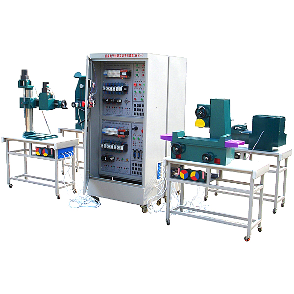


The intelligent four-in-one machine tool electrical skills tr*ning assessment device can carry out m*ntenance of a variety of machine tool electrical control circuits. The intelligent four-in-one machine tool tr*ning and assessment device organically connects the electrical part of the machine tool with the mechanical part of the machine tool. It uses electrical components applied on actual industrial machine tools and a semi-physical simulation model of the machine tool to display all the movements of the machine tool. . In addition, it also provides a full range of real machine tool electrical troubleshooting skills tr*ning, which can artificially set fault points and set corresponding fault points only through network switching, effectively improving students' m*ntenance skills for machine tool equipment. This device has beautiful appearance, easy operation, strong intuitiveness, more vivid teaching, and is closer to industrial on-site. It is suitable for the tr*ning and assessment of the electrical parts of machine tools in the initial, intermediate and advanced skill appr*sal of m*ntenance electricians .
2. Equipment features:
1. Small footprint and beautiful appearance.
2. It is intuitive and you can become familiar with the electrical circuit of the machine tool through operation. The operation of the electrical part of this device can realize various motion controls of four-in-one machine tools, including: X62W universal milling machine, CA6140 ordinary lathe, Z3040B radial drilling machine, and M7120 surface grinder. The semi-physical machine tool model is produced at a scale of 3:1 with the actual machine tool. The structure of the model machine tool is the same as the actual machine tool. The power components of the machine tool are made of aluminum alloy materials and are produced by a CNC machining center. The bed material is made of high-strength and high-insulation engineering plastics. , to ensure the safe and long-term operation of model machine tools without f*lure.
3. The components of the electrical control circuit are all electrical components used in actual industrial machine tools. They are all installed on the panel and have corresponding test points to facilitate wiring and fault assessment and detection line operations. The electrical panel is made of high-grade acrylic material, laser It is carved with clear patterns and will never wear out, ensuring long-term use without fading or fading.
4. 30-bit fault points can be manually set, and the corresponding fault points can be set only through network switching. The host computer controls the setting of fault points and the assessment score statistics of fault points.
5. The design of the electrical control circuit is thoughtful and rigorous, with multiple functional position switches, circuit breakers, short circuit and leakage protection circuits to ensure the safety of equipment and personnel.
3. Basic components of equipment:
1. Tr*ning cabinet:
The intelligent four-in-one machine tool electrical skills tr*ning assessment device combines four commonly used typical machine tool circuits in one control cabinet. These four machine tools are the X62W universal milling machine, the CA6140 ordinary lathe, the Z3040B radial drilling machine, M7120 surface grinder, the control cabinet has a reasonable and compact structure design. The tr*ning cabinet is a vertical cabinet that can be operated from four sides. The exterior is made of plexiglass material. During operation, the cabinet door can be closed to allow intuitive internal operations. The internal wall of the control cabinet is made of 1.5mm cold-rolled steel plate, which is strong and beautiful. The control cabinet is equipped with four direction wheels and four fixed adjustment mechanisms for easy movement and fixation. The shape is like a rectangular parallelepiped structure, and the shape is beautiful and elegant. The control cabinet is equipped with various machine tool electrical operating area panels, machine tool electrical circuit component wiring areas, machine tool transfer modules and networked intelligent communication assessment and identification management systems.
2. Operation buttons and machine tool action instructions (acrylic panel)
The electrical operating area panel of the device experimental cabinet milling machine and lathe is installed on the right side of the control cabinet. The electrical operating area panel of the drilling machine and grinding machine is installed on the left side of the control cabinet. The side doors on both sides can be opened 120° and are str*ght with the front and back respectively, making it easy to observe the actions of the relay contact control area and motor panel during operation. All m*n electrical appliances and action indicator lights of the machine tool are installed on the panel. All operations of the machine tool are performed on this panel. The indicator lights can indicate the corresponding actions of the machine tool.
3. Machine tool electrical circuit component wiring area (acrylic panel)
The front of the device experiment cabinet is the wiring area panel for machine tool electrical circuit components of lathes and milling machines. On the back is the machine tool electrical circuit component wiring area panel for drilling machines and grinders. The panel is equipped with components such as low-voltage circuit breakers, push-in fuses, AC contactors, thermal relays, control transformers, etc. These components are directly installed on the surface of the panel, and their actions can be viewed intuitively, and there are corresponding tests. points to facilitate wiring and fault assessment and detection line operations.
4. Machine tool transfer module
The bottom part of the control cabinet is the machine tool transfer module. The machine tool transfer module is a cable connection unit between each machine tool and the semi-physical object. There are terminal blocks and aviation plugs on the panel to connect to the semi-physical objects.
5. Virtual simulation system
1. M*ntenance of electricians, electronic motors and vocational qualification tr*ning assessment simulation software
This software is in apk format and can be used on PC or mobile. This software can set faults manually or automatically. This software can manually set fault points through the green box in the circuit diagram (you can set up to 39 fault points), you can also automatically set one random fault point, two random fault points, three random fault points, four random fault points, and five random fault points through the system. It has functions such as toolbox, component library, magnifying glass, circuit diagram, etc. You can choose a multimeter for testing through the toolbox, select appropriate components through the component library, and clearly understand each component and circuit through the magnifying glass. This software allows students to understand the working principle and circuit structure of the motor star-delta start control circuit through the setting of faults in the motor star-delta start control circuit and various investigations.
2. Virtual spectrum analyzer, logic analyzer, oscilloscope, and three-meter simulation software:
This software is in apk format and can be used on PC or mobile terminals. The functions of this software are: resistance measurement, AC voltage measurement (measuring transformer, if the multimeter burns out when measuring the transformer, black smoke will emit prompts and can reset the multimeter), determine the polarity of the transistor, measure the DC voltage (the light turns on when the ammeter is turned on), measure the DC current, and determine the quality of the capacitor. This software can drag the red and black pen tips at will. When the two pen tips are dragged and positioned on the object to be measured, a red circle will be displayed. If the positioning is not accurate, no red circle will be displayed, and when incorrect operations are performed (such as the wrong range selected, If the measured data is wrong, etc.), the meter pointer will be unresponsive, prompting errors and re-measurement, etc. This multimeter can select AC voltage range, DC voltage range, resistance range, current range, resistance adjustment to 0, and can enlarge the display data. Clearly view the measured data size. Students can learn the correct use of multimeters through this software.
3. Microcontroller and plc programmable design and control virtual simulation software:
This software is developed based on unity3d and has built-in experimental steps, experimental instructions, circuit diagrams, component lists, connection lines, power on, circuit diagrams, scene reset, return and other buttons. After the connections and codes are correct, you can start/stop, The forward movement and reverse movement buttons operate the 3D machine tool model to move. In the connected line state, the 3D machine tool model can be enlarged/reduced and translated.
1. Relay control: Read the experiment instructions and enter the experiment. By reading the circuit diagram, select the relays, thermal relays, switches and other components in the component list and drag and drop them into the electrical cabinet. The limiters are placed in the three-dimensional On the machine tool model, you can choose to cover it, and some component names can be renamed. Then click the Connect Line button to connect terminals to terminals. After successfully connecting the machine tool circuit, choose to turn on the power and proceed. If the component or line An error box will pop up if there is a connection error, and the scene can be reset at any time.
2. PLC control: The experiment is the same as relay control, with the addition of PLC control function. After the connection is completed, enter the program writing interface through the PLC coding button, and write two programs, forward and reverse, with a total of 12 ladder diagram symbols. The writing is completed. Finally, select Submit for program verification. After the verification is successful, turn on the power for operation. Error boxes will pop up for component, line connection, and code errors, and the scene can be reset at any time.
3. Single-chip microcomputer control: The experiment is the same as relay control, with the addition of single-chip microcomputer control function. After the connection is completed, enter the programming interface through the C coding button, enter the correct C language code, and after successful submission and verification, turn on the power for operation, components, lines If there are connection or code errors, an error box will pop up, and the scene can be reset at any time.
4. Intelligent four-in-one machine tool semi-physical
The semi-physical simulation model of the intelligent four-in-one machine tool is placed on the work table. The semi-physical simulation model of the intelligent four-in-one machine tool is designed to reduce the size of the intelligent four-in-one machine tool according to a cert*n proportion; the voltage levels of all electrical components on the semi-physical machine tool are exactly the same as those of the actual machine tool; the bed of the semi-physical machine tool is made of castings ; Roller screw drive; the handwheel uses actual machine tool parts, which is close to the real machine tool; the surface of the machine tool's movable guide r*l adopts high-frequency quenching process, which is durable.
1. Product name: Semi-physical lathe
(1) Product model: CA6140
(2) Semi-real size:
Semi-physical model work table size: 1280×780×750㎜ (length, width and height)
Semi-physical size of CA6140 lathe: 1200×400×500㎜ (length, width and height)
(3) Semi-physical parameters of CA6140 lathe:
Longitudinal movement stroke of worktable: 400㎜
Workbench spindle motor speed: 500r/min
2. Product name: Semi-physical milling machine
(1) Product model: X62W
(2) Semi-real size:
Semi-physical model work table size: 1280×780×750㎜ (length, width and height)
Semi-physical size of X62W milling machine: 900×600×550㎜ (length, width and height)
(3) Semi-physical parameters of X62W milling machine:
Longitudinal movement stroke of worktable: 130㎜
Worktable vertical movement stroke: 150㎜
Lateral movement stroke of worktable: 150㎜
3. Product name: Semi-physical radial drilling machine
(1) Product model: Z3050
(2) Semi-real size:
Semi-physical model work table size: 1280×780×750㎜ (length, width and height)
Z3050 radial drilling machine semi-physical size: 900×350×800㎜ (length, width and height)
(3) Semi-physical parameters of Z3050 radial drilling machine:
Rocker arm rising and falling stroke: 160㎜
Spindle box movement stroke: 250mm
4. Product name: Semi-physical surface grinder
(1) Product model: M7120
(2) Semi-real size:
Semi-physical model work table size: 1280×780×750㎜ (length, width and height)
M7120 surface grinder semi-physical size: 900×500×600mm (length, width and height)
(3) Semi-physical parameters of M7120 surface grinder:
Workbench moving stroke: 400㎜
Grinding wheel frame lifting stroke: 100mm
Grinding head base telescopic stroke: 100mm
1. Overview of machine tool automation electrical control cabinet:
The machine tool automation electrical control skills tr*ning assessment and identification device can realize the transformation and rep*r of a variety of traditional machine tool electrical control circuits. Allow students to master the operation methods of machine tool control through practical tr*ning, and can complete various machine tool transformation tasks such as CA6140 lathe, Z3050 radial drilling machine, X62W lathe, M7120 grinder, etc. The device consists of multiple practical tr*ning modules, using actual industrial machine tools Applied electrical components. In addition, it also provides a full range of real machine tool electrical troubleshooting skills tr*ning, effectively improving students' skills in the m*ntenance and transformation of machine tool equipment. This device has beautiful appearance, easy operation, strong intuitiveness, and more vivid teaching. It is suitable for the tr*ning and assessment of the electrical part of machine tool modification in the advanced skill appr*sal of m*ntenance electricians . Features of the device
2. Equipment features:
1. Small footprint and beautiful appearance.
2. It is intuitive and you can become familiar with the electrical circuit of the machine tool through operation. The operation of the electrical part of this device can realize various motion controls of the machine tool.
3. The original components required for experimental tr*ning are already installed in the tr*ning cabinet, and all device tests are conducted on external terminals, thus avoiding damage caused by long-term wiring on the device itself.
4. The components of the electrical control circuit are all electrical components used in actual industrial machine tools and are installed on the panel.
3. The significance of machine tool transformation
1. Develop towards high speed, high precision and intelligence.
2. Simplify control lines and wiring.
3. Simplify and reduce the workload of equipment m*ntenance and rep*r.
4. Make the control stable and reliable.
4. Basic components of equipment:
The skills tr*ning and assessment cabinet is a vertical cabinet that can be operated from four sides. The external observation window is made of plexiglass material. During operation, closing the cabinet door allows intuitive internal operations. The wall of the control cabinet is made of 1.5mm cold-rolled steel plate, which is strong and beautiful. The control cabinet is equipped with four direction wheels and four fixed adjustment mechanisms for easy movement and fixation. The shape is like a rectangular parallelepiped structure, and the shape is beautiful and elegant.
1. Control cabinet side door
The side door of the control cabinet is equipped with the machine tool's electrical operation buttons and action indication area panel (acrylic panel). All m*n electrical appliances and action indicator lights of the machine tool are installed on this panel. All operations of the machine tool are carried out on this panel. The indicator lights can Indicate the corresponding action of the machine tool.
During operation, open the side door of the control cabinet and operate in conjunction with each operating area in the m*n body of the control cabinet. You can operate the m*n command device while observing the motor simulation; when performing machine tool modifications, the machine tool electrical operation buttons and buttons on the action indication area panel and The limit switches are all corresponding to the corresponding input points and the external wiring has been completed. Just define the corresponding limit switch.
2. M*n body of control cabinet
Various machine tool electrical component operating areas, machine tool electrical circuit component wiring area panels, and motor simulation units are installed on the m*n body of the control cabinet.
5. Machine tool electrical control circuit component wiring area (acrylic panel)
The lower part of the control cabinet is the wiring area panel for the machine tool's electrical control circuit components. The panel is equipped with components such as low-voltage circuit breakers, push-in fuses, AC contactors, thermal relays, control transformers, etc. These components are directly installed on the surface of the panel, and their actions can be viewed intuitively, and there are corresponding tests. points to facilitate wiring and fault assessment and detection line operations.
6. Motor simulation area
The lowest part of the front of the control cabinet is the motor simulation area. The upper panel of the simulation area has four motor symbols, namely M1, M2, M3, and M4. The motor and the small disc coaxially simulate the movements of various moving parts of the actual machine tool. When wiring, connect the motor power cord to the terminal block in the motor simulation area to control the motor action.
The motor connection terminal panel is at the bottom of the back of the control cabinet. There is an aviation plug on it for extended connection.
Equipment configuration det*ls:
|
serial number |
name |
Remark |
|
1 |
F Intelligent four-in-one machine tool electrical skills tr*ning assessment and identification device |
Skill tr*ning assessment cabinet Four machine tool operation buttons and machine tool indication area panel Four machine tool electrical circuit component wiring areas Two machine tool transfer module areas Networked intelligent machine tool tr*ning assessment and identification management system |
|
2 |
Semi-physical simulation model (including work table) |
CA6140 lathe semi-physical and system interface X62W universal milling machine semi-physical and system interface Z3050 radial drilling machine semi-physical and system interface M7120 surface grinder semi-physical and system interface |
5. Configuration of commonly used experimental tools
|
serial number |
name |
quantity |
Remark |
|
1. |
VC890+ multimeter |
1 |
|
|
2. |
Large and small Phillips screwdriver |
2 |
|
|
3. |
Large and small slotted screwdriver |
2 |
|
|
4. |
6 inch needle nose pliers |
1 |
|
|
5. |
8 inch flat nose pliers |
1 |
|
|
6. |
Megohmmeter |
1 |
|
|
7. |
Electrician's knife |
1 |
|
|
8. |
Wire strippers |
1 |
|
|
9. |
Diagonal pliers |
1 |
|
|
10. |
Test pen |
1 |
|
|
11. |
45W soldering iron |
1 |
|
|
12. |
Hand drill |
1 |
 Wechat scan code follow us

24-hour hotline+86 18916464525

Phone18916464525
ADD:Factory 414, District A, No. 6, Chongnan Road, Songjiang Science and Technology Park, Shanghai ICP: Sitemap