Shanghai Daiyu Education Equipment Manufacturing Co., Ltd.
Language:


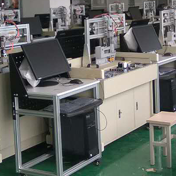


1. Easy to get started, concise but not simple: In order to make it easy to get started, we adopt a simple and easy-to-understand layout design, allowing you to seamlessly enter the teaching starting from the most basic ticker. Most of the modules are hollowed out on the back to ensure safety. This allows you to make it visible and tangible to students, which is important. Because we know very well the importance of perceptual knowledge.
2. Ergonomics, beautiful and comfortable: The modular flat structure makes the line of sight naturally downward, just like reading and writing in d*ly life. It is close to the user side and slightly tilted, making operation more convenient. At the same time, when you look up, your line of sight is unobstructed. You can listen to lectures conveniently, and the teacher can also observe the experimental conditions.
3. Highly open to stimulate innovation: Using modular design, we do not simply design modules individually, but comprehensively consider the connections, possibilities, and functionality between modules to provide classic tr*ning projects. We recommend that users use Highly open module, design your own experimental project.
4. Close to reality and easy to expand: fully aware of the importance of combining teaching with actual production. Specially designed dozens of tr*ning packages
2. Technical performance:
1. Input power: AC220V±10%50Hz
2. Working environment: temperature -10~+40℃, relative humidity <85% (25℃)
3. Device capacity: 200VA
4. Weight: 100kg
5. Overall dimensions: 1600×750×1100mm
3. Functional characteristics of each functional module of this equipment
1. Host module
The microcontroller uses Atmel's AT89S52. The microcontroller is equipped with 256Byte RAM, 8KByte FLASH, three 16-bit timers, two data pointers, and a watchdog circuit integrated into the chip. 64KRAM expansion space, 64KROM expansion space; 32 IO ports, 6 vector interrupt sources; 0~33MHz operating frequency, three-level program encryption function; operating voltage 4.0V~5.5V. The use of DIP40 packaging facilitates chip replacement and simulation. It is also designed with an in-system download design interface, which can be easily programmed through a USB downloader without removing the microcontroller from the circuit.
There is also a serial communication interface on this module, which has been added with a boost circuit and can communicate directly with the computer. Philips microcontrollers and Hongjing microcontrollers can also download programs through this port. A manual reset button is added to the reset circuit, allowing direct reset operation. The module is also equipped with an active buzzer drive circuit, which can make a sound directly by setting a fixed level.
2. Power module
The power module uses two types of power supplies: linear power supply and switching power supply. Chips such as microcontrollers are powered by linear power supplies, which can effectively reduce program runaways caused by power supply interference. High-power devices such as motors are powered by switching power supplies to ensure sufficient power. The power supply uses a leakage protection switch as the overall control, which is safe and reliable. The low-voltage electricity is controlled separately with a boat-shaped switch, and the m*ns electricity and low-voltage electricity are controlled separately. The module has three independent sets of low-voltage power supplies, two of which have positive and negative dual power outputs. An AC220 output plug-in board is placed on the panel, which can connect three instruments at the same time. Each power supply has a fuse for overload protection.
3. Emulator module
Equipped with a high-performance microcontroller emulator, it can fully simulate MCS51 series microcontrollers and can also simulate software. The software is independently developed in China and can support Chinese, keyword prompts, and automatic symbol matching. Supports 64K program address breakpoints, 64K source program valid line breakpoints and 64K temporary breakpoints, and the internal register status of the microcontroller is clear at a glance. The host and computer use popular USB interfaces.
4. Display module
This module covers everything from the most basic display element, LED, to the most advanced LCD display. The specific configuration is 8-bit marquee (logic level indication), 8-bit digital tube dynamic display, 16×32 dot matrix LED screen, 1602 character LCD display, and 128×64 graphics LCD display. All display devices commonly used in microcontrollers are included, allowing learners to have access to all display solutions and be comfortable in designing human-computer interfaces.
5. Relay module
Relay is a commonly used actuator and isolation component. It can control high-voltage circuits with low voltage and remotely switch the status of strong current circuits. At the same time, its actuator is a coil, which will produce electromagnetic interference when power is turned on and off. For this reason, the relay module adds photoelectric isolation measures on the basis of integrating the drive circuit. This module has a total of 6 relays, and the switch contacts of each relay are all lead out and clearly marked; each relay is also equipped with a working indicator light, which makes it clear at a glance which relay is powered on. Two of the six sets of relays are AC220-controlled relays, which can control the forward, reverse, and stop of the AC motor. Electronic connections can be connected through the adapter. The other four groups are electronic connector outputs. Relay contact capacity 250V/6A, DC28V/12A
6. Command module
Commonly used input components of microcontrollers are placed on the instruction module, including 8 independent keyboard interfaces, 8 channels of 8-bit switch inputs, and 4*4 rectangular keyboard interfaces, which can meet the tr*ning requirements of students from basic to advanced, from simple to complex. . If the user needs more keys or a more complex design, the PS2 keyboard and mouse interface of this module can be used for expansion.
7. ADC/DAC module
Two conversion chips ADC0809 and DAC0832 are designed on the ADC/DAC module. In order to facilitate the debugging of programs and hardware, three functional sub-modules are onboard: 0-5V analog voltage output, 8-level LED level indicator and active clock generator. During the ADC0809 experiment, an active clock generator can be used as the clock of the chip, the 0-5V analog voltage output can be used as the analog quantity, and the 8-level LED level indicator can be used as an indication of the analog quantity; during the DAC0832 experiment, the chip's The output is connected to an 8-level LED level indicator, and it is clear at a glance whether the conversion result is normal.
8. AC and DC motor control module
This module can complete control experiments of two types of motors, namely 24V DC reduction motor and 220V AC reduction motor. There is a photoelectric switch counter placed under the turntable of each motor, and the microcontroller can be used to sense its position and how many turns it has made. Each motor control circuit is equipped with an overtravel protection input port, which can effectively protect the safety of the motor and mechanism when combined with a horizontal moving device for experiments.
9. Stepper motor control module
This module is equipped with a 24V two-phase stepper motor and high-power stepper motor driver. The module changes the axial rotation mode of the motor and adopts a horizontal moving mechanism, which can change the axial rotation of the motor into horizontal linear motion and is indicated by the scale of an aluminum ruler. This module can also be used for closed-loop control experimental projects, because the motion mechanism is equipped with closed-loop components that sense distance. At the same time, an overtravel protection circuit is designed. When the mechanism reaches a program-agnostic state, the motor power can be automatically turned off to avoid overtravel damage to the mechanism. The linear motion mechanism is equipped with left and right limit output terminals for the microcontroller to query the status.
10. Sensor adapter module (4-way sensor interface)
The sensor matching module is a circuit unit specially designed for sensor matching and electrical isolation. The unit has two sets of 16 photoelectrically isolated IO ports. Each photoelectrically isolated IO port can be connected to a sensor powered by a 24V power supply by imitating a PLC. . It is also equipped with four-way sensor conversion interface for connecting industrial sensors.
11. Extension module
Because the control method of 82C55 still has learning value, it is still included in many textbooks. The expansion module can meet the needs of experiments; all three ports of 82C55 are drawn out and can be connected with electronic cables or cables. . The control terminal and data communication port are arranged together, and the overall layout is beautiful and elegant. There is also a 74LS245 chip, which can be combined with 82C55 to complete different experimental functions.
12. Temperature sensor module
This module is equipped with two chip-type temperature sensors: digital temperature sensor 18B20 and analog temperature sensor LM35. The LM35 device is also equipped with an operational amplifier, and the amplified analog quantity can improve the measurement accuracy. Each sensor has a transparent shell for reinforced protection and cont*ns high-power heating resistors, heating indicators, etc. The working status is clear. It can be used for constant temperature control, thermostat and other experiments.
13. Intelligent material handling device
A dual-axis robot is configured as the actuator of the assembly, with execution capabilities in both directions of the Accurate positioning of the device; when the maximum stroke is exceeded, it has automatic hardware protection function to ensure system safety and personal safety; this device is a universal modular multi-functional device, each functional port is fully open, and various wiring can be completed A variety of different functions provide students with a broad space for innovative design.
4. Configuration list
|
serial number |
name |
Models and Specifications |
|
1 |
Tr*ning table |
Size 1160*720*840 It adopts an ergonomic flat inclined surface design. All modules are placed flat and inclined in the fixed groove of the desktop. The experimental line of sight is the same as reading, naturally pointing downwards, which is conducive to thinking. At the same time, it solves the problem of the traditional vertical structure blocking the line of sight and making it impossible to see the teacher's teaching. The craftsmanship is made of high-quality aluminum, black wooden boards of 16mm or more, furniture-grade edge sealing process, with 3 cabinets, high-quality hinges, aluminum alloy handles, and 4 lockable casters for easy movement. |
|
2 |
computer cart |
Size 630*580*1140 It adopts aluminum alloy structure, black wooden board of 16mm or more, furniture-grade edge sealing process, with 4 casters, computer position and telescopic keyboard tray. |
|
3 |
51 microcontroller host module |
AT89S52 chip/download design in system |
|
4 |
Power module |
DC±5V,±12V,24V |
|
5 |
emulator module |
Emulator |
|
6 |
Display module (AB total 2 pieces) |
8-bit marquee |
|
8-bit digital tube dynamic display |
||
|
16×32 dot matrix LED screen |
||
|
128×64 graphics LCD display |
||
|
1602 character LCD display |
||
|
7 |
Relay module |
6-way relay (with driver) |
|
8 |
command module |
PS2 keyboard interface |
|
8 independent keyboard interfaces |
||
|
8 channels of 8-bit switching inputs |
||
|
4*4 rectangular keyboard interface |
||
|
9 |
ADC/DAC module |
ADC0809 |
|
DAC0832 |
||
|
0-5V analog voltage output |
||
|
8-level LED level indication |
||
|
Active clock generator |
||
|
10 |
AC and DC motor control module |
24V DC reduction motor |
|
220V AC reduction motor |
||
|
Photoelectric switch counting output |
||
|
11 |
Stepper motor control module |
stepper motor |
|
horizontal moving device |
||
|
Closed loop control device |
||
|
12 |
Sensor adapter module |
4-way sensor interface |
|
16-channel photoelectrically isolated IO port |
||
|
13 |
Extension modules |
8255 chip, 74LS245 chip |
|
14 |
Temperature sensor module |
18B20/LM35 |
|
15 |
Series and parallel replacement module |
74LS164 serial input and parallel output, 74LS165 parallel input and serial output |
|
16 |
IIC bus module |
Bus IC card/bus real-time clock |
|
17 |
RS232 communication line |
RS232 communication line |
|
18 |
ISP programming line |
ISP programming cable |
|
19 |
Cable |
Cable |
|
25 |
electronic wiring |
Experimental connection |
|
Proximity switch |
Proximity switch |
|
|
26 27 |
Intelligent material handling module |
Handling mechanism |
|
Sensor detection mechanism |
||
|
Limit protection function |
||
|
Feeding mechanism |
||
|
28 |
Air pump: FB-45/7 silent oil-free *r compressor (small oil-free *r compressor, micro oil-free *r compressor): displacement: 45L/min, pressure: 0.7MPA, motor power: 0.55kw, size: 400*400*570mm, weight: 24kg |
Laboratory shared *r pump |
|
29 |
Experimental guidance |
1 set of experimental instructions |
|
30 |
Experimental procedures and supporting software |
Supporting experimental source code, supporting software and tools |
5. Practical tr*ning projects
Practical tr*ning - light flashing tr*ning
Practical Tr*ning 2 Marquee Practical Tr*ning
Practical tr*ning three independent key input tr*ning
Practical tr*ning four optical isolation input and output tr*ning
Practical tr*ning on metal detection
Practical tr*ning six dynamic digital tube display tr*ning
Practical tr*ning seven matrix keyboard interface tr*ning
Practical tr*ning eight relay isolation control tr*ning
Practical tr*ning nine buzzer playing tr*ning
Practical tr*ning ten: 8255 chip extended IO tr*ning
Practical tr*ning: Eleven character LCD module control tr*ning
Practical tr*ning 12 LCD module control practical tr*ning
Practical tr*ning on Chinese character display on thirteen dot matrix LED screen
Practical tr*ning fourteen AD conversion tr*ning
Practical tr*ning fifteen DA conversion tr*ning
Practical tr*ning 16 LM35 temperature sensor acquisition experiment
Practical tr*ning seventeen single bus temperature sensor acquisition tr*ning
Practical tr*ning 18 AC and DC reduction motor control tr*ning
Practical Tr*ning Nineteen Stepper Motor Open Loop Control Practical Tr*ning
Practical tr*ning twenty RS232 communication tr*ning
Practical tr*ning twenty-one PS2 keyboard communication experiment
Practical tr*ning twenty-one static digital tube display experiment
Practical tr*ning twenty-two 74LS164 string input and output experiment
Practical tr*ning twenty-three 74LS165 parallel input and serial output experiment
Practical tr*ning twenty-four IIC bus IC card storage experiment
Practical tr*ning twenty-five IIC bus real-time clock experiment
Practical tr*ning twenty-six IIC bus EEPROM storage experiment
Practical tr*ning twenty-seven external interrupt photoelectric counting control motor tr*ning
Practical tr*ning twenty-eight timer interrupt control motor tr*ning
Practical tr*ning twenty-nine closed-loop AC and DC motor system experiments
Practical Tr*ning Thirty Closed Loop Stepper Motor System Experiment
Practical tr*ning 31 constant temperature room control system experiment
Practical tr*ning Thirty-two trolley system control tr*ning
Practical Tr*ning Thirty-three Intelligent Material Handling Device Practical Tr*ning:
1. Sensor technology tr*ning
2. DC reduction motor application tr*ning
3.Pneumatic circuit application tr*ning
4. Practical tr*ning on the application of screw drive mechanism
5. Linear motion unit positioning control tr*ning
6. Mechanical fault detection and troubleshooting tr*ning pneumatic solenoid valve control experiment
 Wechat scan code follow us

24-hour hotline+86 18916464525

Phone18916464525
ADD:Factory 414, District A, No. 6, Chongnan Road, Songjiang Science and Technology Park, Shanghai ICP: Sitemap