Shanghai Daiyu Education Equipment Manufacturing Co., Ltd.
Language:


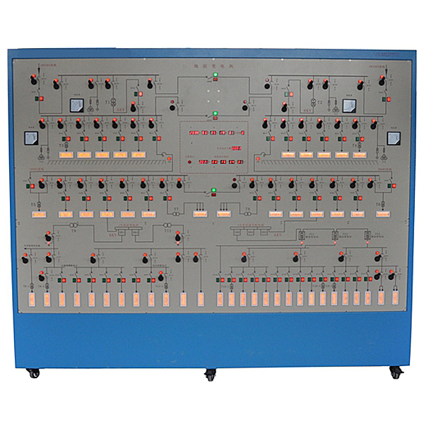


The "Mine Power Supply System Simulation Operation Device" is designed based on a typical mine power supply system, including the underground power supply part, the underground central substation part, the mining area working surface power supply part, the mobile substation power supply part, etc. Through the tr*ning of this device, students can have a comprehensive understanding of the mine power supply system, and can complete the switching operation of the power supply system. It is also equipped with a misoperation alarm, which can be used as a safety tr*ning and assessment for mine electrical personnel.
2. Technical parameters
1. Input power: three-phase five-wire ~ 380V ±10% 50Hz
2. Working environment: ambient temperature -5℃~+40℃, relative humidity <85% (25℃), altitude <4000m
3. Overall dimensions: 2400mm×500mm×2000mm
3. Device configuration
1. Device structure
The device adopts a cabinet structure. The cabinet adopts a double-layer matte dense pattern spray-plastic structure. The panel is made of 2mm thick aluminum plate. The text symbols on the panel adopt spray-plastic process. The cabinet is equipped with six universal wheels for easy movement and fixation.
2. Power supply system
The front of the control panel is a simulated operation panel of a typical mine power supply system. The device is powered by dual power supplies. The system is divided into five parts:
(1) Ground 35kV power supply part (dual power supply)
(2) Ground 6kV power supply part (auxiliary shaft hoist, m*n hoist, ventilator, *r compressor, etc.)
(3) 6kV power supply part of underground central substation (hoist, rectifier equipment, water pump, low-voltage power lighting, etc.)
(4) The substation part of the mining area (coal electric drill)
(5) Power distribution part of mobile substation in mining area (coal shearer)
The m*n switching components in the system are switches and circuit breakers. Each switch operating component and circuit breaker component on the corresponding system diagram are embedded in the corresponding position of the system diagram. Their on and off are indicated by corresponding signal lights. The red and green signal lights indicate closing and opening respectively. brake. Each power supply branch has a corresponding load and is indicated by a light plate.
3. Misoperation alarm and recording module
A misoperation alarm and recording module is installed on the front of the gate screen. The misoperation alarm and recording module has the function of intelligently identifying whether the student's operation is correct. If the operation is incorrect, the gate screen will immediately send out an audible and visual alarm indication and record the number of misoperations. After a misoperation, the user needs to correct the misoperation and press the reset button to reset the audible and visual alarm before proceeding to the next step.
The side of the control panel is equipped with a "Misoperation Clear" button and two toggle switches that simulate leakage detection relay f*lures; press the "Misoperation Clear" button to clear the misoperation record on the switching screen panel; toggle Toggle switches "K1" and "K2" can simulate the f*lure of the leak detection relay.
4. Settings of clock display module
A clock display module is installed in the upper center of the control screen, which can be set through the remote control. This module can be used as a clock at ordinary times, accurately displaying "year, month, day, hour, minute, week", and can record the "day" of the safe operation of the power supply system. "Number; can also be used as the time basis for practical tr*ning assessment.
5. Instruments and light plates
The voltmeter on the control panel indicates the voltage on the 35kV bus and 6kV bus of the substation respectively, and the left and right sides indicate the two power supplies respectively; the measuring ranges are 0~40kV and 0~6kV respectively, and the accuracy is 1.0 level;
The light plate represents the load on each branch. When the corresponding branch is connected, the light plate lights up.
4. Practical tr*ning content
1. Structure, composition and operation cognition of mine power supply system
2. Understand the switching operation and fill in the operation ticket
3.35kV bus runs in parallel, 6kV bus runs in parallel
4. Switching operation from one incoming line power supply to two lines of power supply
5.6kV bus power transmission and switching operation
6. Power transmission and switching operation of underground central substation
No. 7.1 mining area substation power switching operation
 Wechat scan code follow us

24-hour hotline+86 18916464525

Phone18916464525
ADD:Factory 414, District A, No. 6, Chongnan Road, Songjiang Science and Technology Park, Shanghai ICP: Sitemap