Shanghai Daiyu Education Equipment Manufacturing Co., Ltd.
Language:


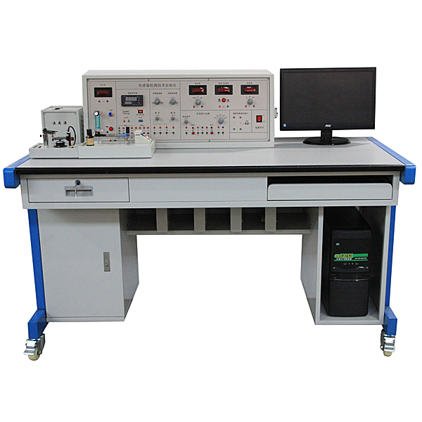


The sensor and detection technology experimental bench consists of six parts: m*n console, vibration source, temperature source, rotation source, sensor and corresponding experimental template, data acquisition card and processing software, and experimental bench.
1. M*n console part
It provides eight types of highly stable DC regulated power supplies: ±15V, +5V, ±2V~±10V adjustable, +2V~+24V adjustable; the m*n console panel is also equipped with voltage, frequency, and speed displays. Audio signal source (audio oscillator) 1KHz~10KHz (adjustable); low-frequency signal source 1Hz~30Hz (adjustable); *r pressure source 0-20kpa adjustable, digital voltmeter: range 0~20V, high accuracy; frequency/speed Table: Frequency 1~9999Hz, speed 1~9999rpm; timer: 0~9999s, accurate to 0.1s; high-precision temperature adjustment instrument (control temperature accuracy ±0.5℃); RS232 computer serial interface.
2. Three-source board
Heating source: 0~220V AC heating, temperature control at room temperature~150℃; Rotation source: 2~24V DC drive, speed adjustable from 0~3000rpm; Vibration source: vibration frequency 1Hz~30Hz (adjustable), resonant frequency around 12Hz .
3. LABVIEW data acquisition card and processing software:
The data collection and interface parts adopt USB interface to facilitate users' actual use. This collector can not only meet complete experimental requirements, replace the existing instrument display readings, but can also be used by scientific researchers for direct scientific research and development. The specific technical indicators are as follows:
1) 3-channel 16-bit input, maximum clamping ±20v, must be implemented to prevent channel burning. The minimum resolution is 1mv, the maximum continuous sampling frequency is 100khz, and the curve must be smooth. M*ntenance of electrical and electronic motors and vocational qualification tr*ning assessment simulation software (copyright certificate and on-site demonstration provided): This software is in apk format and can be used on the PC or mobile terminals. This software can manually set faults or automatically To set the fault, the software can manually set the fault point through the green box in the circuit diagram (up to 39 fault points can be set), or the system can automatically set one random fault point, two random fault points, and three random faults through the system. Point setting, random four fault point settings, random five fault point settings, this software has toolbox, component library, magnifying glass, circuit diagram and other functions. You can select a multimeter for detection through the toolbox, and select appropriate components through the component library , you can clearly understand each component and circuit through a magnifying glass. This software allows students to understand the working principle and circuit structure of the motor star-delta start control circuit through the setting of faults in the motor star-delta start control circuit and various investigations.
2) All sensor experimental sampling and control software must be collected and controlled using labview. Software acquisition settings can be divided into single-step sampling, scheduled sampling, two-way sampling, and dynamic sampling. During single-step sampling, the maximum nonlinear error or maximum hysteresis error can be analyzed by the least squares method and the endpoint method. During dynamic experiments, the frequency, amplitude or rotation speed of the input waveform can be analyzed. Supports printing function, the experimental results can be printed out after the experiment is completed. The acquisition card hardware has a programmable amplification function and can achieve high accuracy when measuring small voltages. The resolution is 1mv. Students can program and debug by themselves.
3) Three-meter simulation software (copyright certificate and on-site demonstration provided):
This software is in apk format and can be used on PC or mobile terminals. The functions of this software are: resistance measurement, AC voltage measurement (measuring transformer, if the multimeter burns out when measuring the transformer, black smoke will emit prompts and can reset the multimeter), determine the polarity of the transistor, measure the DC voltage (the light turns on when the ammeter is turned on), measure the DC current, and determine the quality of the capacitor. This software can drag the red and black pen tips at will. When the two pen tips are dragged and positioned on the object to be measured, a red circle will be displayed. If the positioning is not accurate, no red circle will be displayed, and when incorrect operations are performed (such as the wrong range selected, If the measured data is wrong, etc.), the meter pointer will be unresponsive, prompting errors and re-measurement, etc. This multimeter can select AC voltage range, DC voltage range, resistance range, current range, resistance adjustment to 0, and can enlarge the display data. Clearly view the measured data size. Students can learn the correct use of multimeters through this software.
4. Experimental table: The size of the special experimental table is 1600×800×750 (mm), and a place for a monitor or oscilloscope is reserved on the experimental table. The two special cabinets of the experimental table can place the experimental template, computer host and keyboard respectively.
5. Virtual simulation software for practical tr*ning safety education (copyright certificate and on-site demonstration provided): This software is developed based on unity3d. The software adopts the form of three-dimensional roaming. Movement can be controlled by the keyboard and the direction of the lens can be controlled by the mouse. It is equipped with mechanical safety distance experiments. Safety protection device experiment and basic assessment of mechanical safety protection design. When the experiment is in progress, the three-dimensional roaming screen uses arrows and footprints to prompt the user to move to the experimental location. The circle around the mechanical object shows the working radius. The experimental process is accompanied by a dialog box reminder of the three-dimensional robot.
A. The content of the mechanical safety distance experiment includes the safety distance experiment to prevent upper and lower limbs from touching the danger zone (divided into two fence heights and opening sizes). After selecting to enter, GB23821-2009 "Mechanical Safety to Prevent Upper and Lower Limbs from Touching the Danger Zone" pops up in front of the camera. "Safe Distance" requirements, error demonstration: The experimental process is that after the human body enters the working radius of the mechanical object and is injured, the red screen and voice prompts that the human body has received mechanical damage, and returns to the original position and conducts the next experiment. The last step is the correct approach.
B. Mechanical safety protection device experiments are divided into safety interlock switches, safety light curt*ns, safety mats, safety laser scanners and other protection device experiments. Optional categories (safety input, safety control, safety output, others), manufacturers, products List (safety interlock switch, safety light curt*n, safety mat, safety laser scanner, safety controller, safety relay, safety guardr*l). There is a blue flashing frame reminder at the installation location. Experimental process: select the safety guardr*l and install it, select the safety interlock switch (or select the safety light curt*n, safety mat, safety laser scanner) and install it, select the safety controller and install it in the electrical control box , select the safety relay and install it in the electrical control box, click the start button on the electrical control box. If you enter a dangerous area, the system will sound an alarm and the mechanical object will stop working. Select the reset button on the electrical control box to stop.
C. The basic assessment of mechanical safety protection design requires the completion of the installation of the mechanical safety system, and the correct installation of safety guardr*ls, safety interlock switches, safety light curt*ns, safety mats, safety laser scanners, safety controllers, safety relays, 24V power supplies, signal lights and Emergency stop button. The assessment is divided into ten assessment points. Some assessment points have 3 options, which are freely chosen by the students. After selecting the final 10 assessment points, submit for confirmation, and the system will automatically obt*n the total score and the score of each assessment point. .
D. The software must be on the same platform as a whole and must not be displayed as separate resources.
E. At the same time, we provide customers with the VR installation package of this software to facilitate users to expand into VR experiments. VR equipment and software installation and debugging are not required.
6. Virtual simulation software ( fire protection module) for electrical installation in building buildings and smart buildings (copyright certificate and on-site demonstration provided)
Based on the unity3d design, users can choose different interactive interface sizes according to computer configuration, and six levels of image quality are av*lable. The model in the software can be rotated 360°, enlarged, reduced, and translated. There is a small assistant prompt during the use of the software, the content is as follows:
A. Wet alarm system
1. System overview: Overview of wet alarm system
2. Equipment awareness: equipped with the best viewing angle, equipment det*ls (displaying the introduction or parameters of the equipment), exercises (built-in 6 multiple-choice questions, prompts for correct and incorrect choices), schematic diagram (can be entered from the schematic diagram) into the device). Equipment includes: nozzle, water flow indicator, signal butterfly valve, exhaust valve, fire alarm control, high pipe pressure gauge, high water tank, Wia control cabinet, pressure stabilizing tank, flow switch, terminal water testing device, dr*nage facilities, water pump connection alarms, hydraulic alarms, delayers, wet alarms, butterfly valves, check valves, fire pumps, safety pressure regulators, and fire pools.
3. Principle display: Show the working principle of the wet alarm system, three-dimensional animation demonstration, the three-dimensional model is translucent, and the internal water flow can be seen. Equipped with practice module (built-in 4 multiple-choice questions, with prompts for correct and incorrect choices)
4. Design layout: There are multiple choice questions and calculation questions. Each question is scored. The correct answer and score will be displayed after submission.
B. Gas fire extinguishing system
1. System overview: Overview of gas fire extinguishing system
2. Equipment awareness: equipped with the best viewing angle, equipment det*ls (displaying the introduction or parameters of the equipment), exercises (built-in 8 multiple-choice questions, prompts for correct and incorrect choices), schematic diagram (can be entered from the schematic diagram) into the device). Equipment includes: nozzle, HFC-227 storage bottle, bottle head valve, heptafluoropropane one-way valve, high-pressure hose, gas one-way valve, safety valve, weighing alarm, electromagnetic starter, selection valve, smoke alarm, fire Alarm controller.
3. Principle display: Show the working principle of the gas fire extinguishing system, three-dimensional animation demonstration, the three-dimensional model is translucent, and the internal gas can be seen. Equipped with practice module (built-in 3 multiple-choice questions, with prompts for correct and incorrect choices)
4. Design layout: There are 6 multiple-choice questions, each question is scored, and the correct answer and score will be displayed after submission.
C. Escape drill: Teaching is conducted in the form of fun games. Escape from the burning room within a limited time. If you make a wrong choice, you will directly enter the score interface.
3. Product features
1. The structure of the sensor has changed from a principle type to an industrial detection sensor. The sensor has changed from qualitative to quantitative. It has a cert*n degree of accuracy and is more convenient for computer-based characteristic analysis of experiments.
2. The instrument is equipped with temperature source, *r source, vibration source and rotation source. The sensors are equipped with corresponding experimental modules for easy operation and management. After the experiment is completed, they can be placed in the cabinet and sensor box of the experimental bench. Some enhanced sensors and their modules can be added according to teaching needs, or special sensor modules can be produced.
3. Various public sources can also be used for student course design, graduation projects and some developmental experiments; the power supply and signal source are equipped with protection points to ensure that students will not damage the equipment after misoperation and ensure the safety of students.
4. Product technical indicators
|
serial number |
Sensor name |
Experiment template |
Measuring range |
Linear |
|
1 |
Resistive Str*n Sensor |
Resistance str*n gauge experiment module |
0-500g (200) |
±0.5% |
|
2 |
Diffused Silicon Pressure Sensor |
Pressure sensor experimental module |
4-20kpa |
±1% |
|
3 |
Differential transformer |
Differential Transformer Experiment Module |
±4mm |
±2% |
|
4 |
capacitive sensor |
Capacitive sensor experimental module |
±2.5mm |
±3% |
|
5 |
Integrated Hall displacement sensor |
Hall sensor experimental module |
±1mm |
±3% |
|
6 |
Hall speed sensor |
2400 rpm |
±0.5% |
|
|
7 |
Magnetoelectric sensor |
|
2400 rpm |
±0.1% |
|
8 |
Piezoelectric sensor |
Piezoelectric sensor experimental module |
||
|
9 |
Eddy current displacement sensor |
Eddy current displacement experiment module |
1mm |
±2% |
|
10 |
Fiber optic displacement sensor |
Optical fiber displacement experiment module |
1mm |
±5% |
|
11 |
Photoelectric speed sensor |
|
2400 rpm |
±0.5% |
|
12 |
Integrated temperature sensor |
Temperature sensor experimental module |
Normal temperature -120℃ |
±3% |
|
13 |
Pt100 platinum resistor |
Normal temperature -150℃ |
±3% |
|
|
14 |
Cu50 copper resistor |
Normal temperature -100℃ |
±3% |
|
|
15 |
K type thermocouple |
Normal temperature -150℃ |
±2% |
|
|
16 |
E type thermocouple |
Normal temperature -150℃ |
±2% |
|
|
17 |
gas sensor |
50-2000PPm |
||
|
18 |
Humidity sensor |
10-95%RH |
||
|
19 |
Phase sensitive detection, phase shifting, filtering |
5. Experimental projects
1. Metal foil str*n gauge single-arm bridge performance experiment
2. Metal foil str*n gauge half-bridge performance experiment
3. Metal foil str*n gauge full-bridge performance experiment
4. Performance comparison experiment of metal foil str*n gauge single arm, half bridge and full bridge
5. Temperature effect experiment of metal foil str*n gauge
6. Application of DC full bridge - electronic scale experiment
7. Application of AC full bridge - vibration measurement experiment
8. Pressure measurement experiment of diffused silicon piezoresistive pressure sensor
9. Differential Transformer Performance Experiment
10. Experiment on the influence of excitation frequency on differential transformer characteristics
11. Differential transformer zero point residual voltage compensation experiment
12. Application of differential transformer - vibration measurement experiment
13. Experiment on displacement characteristics of capacitive sensor
14. Capacitive sensor dynamic characteristics experiment
15. Experiment on displacement characteristics of Hall sensor under DC excitation
16. Experiment on displacement characteristics of Hall sensor under AC excitation
17. Hall speed test
18. Speed measurement experiment of magnetoelectric speed sensor
19. Measuring earthquakes using the magnetoelectric principle*
20. Piezoelectric sensor vibration measurement experiment
twenty one. Experiment on displacement characteristics of eddy current sensor
twenty two. Experiment on the influence of the material of the measured object on the characteristics of the eddy current sensor
twenty three. The size of the measured object affects the eddy current sensor's
Characteristic impact experiment
twenty four. Eddy current sensor vibration measurement experiment
25. Eddy current sensor speed measurement experiment*
26. Displacement Characteristics Experiment of Optical Fiber Sensor
27. Fiber optic sensor measurement vibration experiment
28. Speed measurement experiment of photoelectric speed sensor
29. Other solutions for measuring rotational speed using photoelectric sensors*
30. Temperature characteristics experiment of integrated temperature sensor
31. Platinum resistance temperature characteristics experiment
32. Copper resistance temperature characteristics experiment*
33. K type thermocouple temperature measurement experiment
34. E-type thermocouple temperature measurement experiment
35. J-type thermocouple temperature measurement experiment*
36. Thermocouple cold end temperature compensation experiment*
37. Principle experiment of alcohol-sensitive gas sensor
38. Humidity sensor experiment
39. Thermal sensor temperature measurement experiment
40. Phase shifter experiment
41. Data acquisition system experiment (static example)
42. Data acquisition system experiment (dynamic example)
Note: The experiments marked with * are thought experiments and should be set up by students themselves.
 Wechat scan code follow us

24-hour hotline+86 18916464525

Phone18916464525
ADD:Factory 414, District A, No. 6, Chongnan Road, Songjiang Science and Technology Park, Shanghai ICP: Sitemap