Shanghai Daiyu Education Equipment Manufacturing Co., Ltd.
Language:


Equipment entrances are equipped with leakage protectors.
The control power supply of the entire experimental system (including the relay auxiliary voltage) adopts a DC 24V power supply within the safe voltage. The experimental signals are required to be output in accordance with the secondary standards of the power system, and the output power is strictly controlled to eliminate the risk of electric shock.
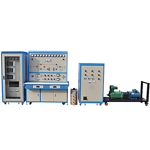
1. Generator set control panel
The generator set control panel is connected to the generator set to complete the excitation regulation, speed regulation and system parallel functions of the generator set, providing conditions for power plant automation.
The generator set control panel consists of measuring instrument unit, speed control system, excitation system, quasi-synchronous device, primary wiring diagram, three-phase analog circuit breaker, mutual inductor, excitation rectifier module, speed control rectifier module, etc.
Measuring instrument unit: including two DC voltmeters and two DC ammeters, which respectively indicate the armature voltage and current of the prime mover, and the excitation voltage and current of the generator; two AC voltmeters, which indicate the terminal voltage and system voltage respectively; two frequency meters Only one, indicating the terminal frequency and system frequency respectively; one three-phase active power meter and one three-phase reactive power meter, respectively indicating the active and reactive loads of the generator set.
Equipment operating parameters:
The operating voltage of the equipment is AC380V, 50Hz. The incoming line is a three-phase five-wire system.
The equipment allows the working environment temperature to be at least within the range of -10℃-+40℃.
The equipment allows the relative humidity of the environment to be no less than 85% (25℃).
The overall capacity of the equipment is less than 10kVA and the current is less than 20A.
2. Power system comprehensive automation experiment system (experiment bench)
The power system integrated automation experiment system test bench provides a typical power system operation primary system.
The experimental bench is composed of a simulated primary m*n system, a multi-functional microcomputer protection device, a short-circuit setting module, and indicating instruments.
Equipment operating parameters:
The operating voltage of the equipment is AC380V, 50Hz. The incoming line is a three-phase five-wire system.
The equipment allows the working environment temperature to be at least within the range of -10℃-+40℃.
The equipment allows the relative humidity of the environment to be no less than 85% (25℃).
The overall capacity of the equipment is less than 10kVA and the current is less than 20A. .
3. Quasi-synchronous device
①. Microcomputer type synchronization device:
a. The accuracy of measuring system frequency, terminal voltage and system voltage is better than 0.5%.
b. Fully automatic synchronous closing.
c. Semi-automatic synchronous closing; circuit breaker closing time measurement.
d. It adopts 800*480 color touch screen display, which is convenient for information input. It is easier to operate than inputting information using buttons. The voltage, frequency and phase angle of the generator side and system side can be displayed on the same screen.
e. Can graphically display the generator set voltage and system voltage rotation vector.
f. Record all electrical parameters (voltage, current, frequency, phase angle, etc.) before and after closing for experimental analysis.
g. Record the voltage and current waveforms of the machine terminal and system for 10 cycles before and after closing, and display them on the display.
h. The device has a network cable interface to communicate with the computer. It can upload the above measurement parameters to the computer for display, and download various parameters of the device.
②. Three-phase analog circuit breaker: simulated with three-phase AC contactor.
③. Analog transformer: Analog step-up transformer, dry-type transformer, 400V/400V, 3kVA.
4. Excitation system
①.Microcomputer type excitation device:
a. Other incentives.
b. It has control modes such as constant machine terminal voltage, constant excitation current, and constant thyristor firing angle.
c. It has excitation limiting functions such as over-excitation limit, under-excitation limit, V/F limit, and stator current limit.
d. It has functions such as PT disconnection protection, no-load overvoltage protection and low-frequency protection.
e. It adopts 800*480 color touch screen display, which is convenient for information input. It is easier to operate than inputting information using keys. It can dynamically display excitation voltage and current waveforms.
f. The frequency, voltage, current, active power, reactive power, excitation voltage and excitation current of the generator are displayed on the same screen.
g. Record all parameters (frequency, voltage, current, active power, reactive power, excitation voltage, excitation current) when the unit becomes unstable for experimental analysis.
h. The device has a network cable interface that can communicate with the computer through the Internet. The above measurement parameters can be uploaded to the computer for display. The computer can remotely adjust the unit through communication and download the device parameter settings.
i. Voltage adjustment range: 20%~120% (stand-alone), 20%~130% (stand-alone test), 85%~120% (grid-connected).
j. Generator voltage regulation accuracy: ≤±0.5%.
k. Starting excitation overshoot ≤10%, load shedding overshoot ≤15%.
l. The adjustment rate is ±15% adjustable.
M. With one-button excitation function
②. Excitation transformer. Three-phase transformer, 2 sets of contacts on the primary side and 2 sets of contacts on the output end. Greater than or equal to 0.8kVA.
③. Excitation rectifier module: controlled by the automatic excitation device to output the generator excitation voltage.
(1) Maximum output current: ≥30A
(2) Rated working voltage: 380V
(3) Control power supply voltage: 12V DC
(4) Control signal: 0~10V
④. Voltage transformer: used to collect the generator terminal voltage.
The transformation ratio is 380V/100V.
⑤. Current transformer: used to collect generator current.
The transformation ratio is 10A/5A.
5. Speed regulating system
①. Microcomputer type speed regulating device:
a. Accuracy of measuring generator speed: ≤0.2%.
b. Measurement system power angle accuracy: ≤1°.
c. Microcomputer automatic adjustment and manual adjustment are possible.
d. It has one-key startup function.
e. Using 800*480 color touch screen display, information input is convenient and easier to operate than using buttons to input information.
f. The device has a network cable interface, which can upload measurement results to a PC and adjust the speed through PC communication.
②. Speed regulating transformer. Three-phase 380, 400/190, 210, 2 sets of contacts on the primary side, 2 sets of contacts on the output end; capacity: ≥3KVA.
③. Speed regulating rectifier module: controlled by the automatic speed regulating device to output the motor driving current.
(1) Maximum output current: ≥30A
(2) Rated working voltage: 380V
(3) Control power supply voltage: 12V DC
(4) Control signal: 0~10V
④. Photoelectric encoder: A photoelectric rotary encoder is used to convert mechanical quantities such as angular displacement and angular velocity of the output shaft into corresponding electrical pulses and output them digitally (REP) through photoelectric conversion.
6. Multifunctional microcomputer protection device
The multi-functional microcomputer protection device can be used in various relay protection experiments and can also be used as a line protection device in power system experiments.
In this system, multi-functional microcomputer protection is configured with line protection function.
Chassis structural dimensions: 210mm×250mm×178mm (4U chassis).
Normal operating temperature: 0~40˚.
Storage and transportation: -25~70˚.
DC power supply: AC voltage input: 220V, allowable deviation: +7%, -10%
DC output: 5V/3A; +12V/0.5A; -12V/0.5A; 24V/0.5A
Frequency: 50Hz
Overload capacity: Current loop: 2 times rated current, continuous operation
10 times rated current, allow 10S
40 times rated current, allow 1S
Voltage loop: 1.5 times rated voltage, continuous operation
Power consumption: AC current: <1VA/phase (In=3A)
<0.5VA/phase (In=0.5A)
The line protection device has functions such as current quick-break protection, time-limited current quick-break protection, over-current protection, inverse-time current protection, zero-sequence voltage protection, reclosing, and overload.
|
function name |
|
|
Protective function |
Three-stage directional current protection |
|
Overcurrent acceleration protection (front acceleration and rear acceleration optional) |
|
|
Inverse time directional overcurrent protection |
|
|
Three-phase one-time reclosing |
|
|
Low cycle load shedding protection |
|
|
Zero sequence overvoltage protection |
|
|
Overload protection |
|
|
Low voltage protection |
|
|
Loss of pressure protection |
|
|
TV disconnection detection |
|
|
Control loop abnormality alarm |
|
|
Measurement and control function |
Remote signaling collection, device remote signaling displacement, accident remote signaling |
|
Normal circuit breaker remote control opening and closing |
|
|
Telemetry of analog quantities such as P, Q, IA, IB, IC, Ua, Ub, Uc, f, COSφ, UAB, UBC, UCA, etc. |
It adopts 800*480 color touch screen display, which is convenient for information input. It is easier to operate than using buttons to input information. It can display voltage, current, frequency, phase angle, switch position, alarm information, action information, etc. on the same screen. The switch position can be displayed graphically.
7. Generator set
(1) Three-phase synchronous generator: SN=2.2KVA, VN=400V
(2) DC motor: PN=2.5KW, VN=220V, IN=13.6A, nN=1500rpm
(3) The speed measuring device adopts photoelectric encoder.
(4) The speed regulating device measures the power angle
(5) Excitation mode: other excitation
(6) The unit is coaxially connected, and the base is equipped with universal wheels, which can be easily moved and fixed during use.
8. Voltage regulator
The voltage regulator terminals are built-in
380V 9kVA three-phase self-coupling voltage regulator
All-round dial, clear scale, easy to operate
Output voltage 0-430V adjustable
Input voltage 380V±10%
Rated output current 20A
Insulation grade A
9. Load
The load is placed inside the table
Load gears are divided into 0.3kW, 0.6kW and 0.9kW
The load size can be reduced or increased by switching on and off the switch
Using general power consumption components, long service life and easy m*ntenance
4. Experimental projects
(1) Generator unit operation experiment
1. Starting and running of prime mover
2. Speed regulating device operation
3. Speed regulating device and prime mover control
(2) Electromechanical experiment of synchronous generator set
1. Starting and running experiment of generator set
2. No-load test and short-circuit test of synchronous generator
3. Synchronous generator V-shaped curve measurement experiment
4. Experiment on external characteristics of synchronous generator
(3) Quasi-synchronous parallel operation experiment
1. Basic operation of microcomputer quasi-synchronous device
1. Automatic quasi-synchronous condition test experiment
2. Pressure difference and frequency difference setting experiment
4. Lead time setting and measurement experiment
5. Manual quasi-synchronous grid connection experiment
6. Semi-automatic quasi-synchronous grid connection experiment
7. Automatic quasi-synchronous grid connection experiment
(4) Generator set excitation experiment
1. Synchronous generator excitation control
2. Basic operation of microcomputer excitation device
(5) Synchronous generator excitation control experiment
1. Excitation voltage experiments corresponding to different α angles (control angles)
2. Excitation and parallel experiments of synchronous generators in typical modes
3. Volt/Hertz Limit Experiment
4. Under-excitation limitation experiment
5. Synchronous generator strong excitation experiment
6. Stator current limitation experiment
7. Adjustment characteristic test experiment
8. Overexcitation limit experiment
9. Forced stimulation experiment
10. Demagnetization experiment
11. Control methods and their mutual switching
(6) Power characteristics and power limit measurement experiments
1. Measurement experiment of power characteristics and power limit when there is no excitation regulation
2. Measurement experiments of power characteristics and power limits when manually adjusting the excitation
3. Measurement experiments of power characteristics and power limits during automatic excitation adjustment
(7) Power system transient stability experiment
1. Experiment on the influence of short circuit types on the transient stability of power systems
2. Experiment on the influence of fault removal time on transient stability
3. Test on the influence of strong excitation on transient stability
(8) Stable operation mode of stand-alone-infinity system
1. Single loop steady-state symmetrical operation
2. Comparison of steady-state symmetrical operation of double-loop and single-loop
3. Single-loop steady-state non-full-phase operation
(9) Single machine load experiment
1. Characteristic experiments of independent systems
2. Experiments on throwing and cutting different loads
(10) Power system stable operation experiment
1. Generator starting and adjustment experiment
2. Power system operation mode experiment
3. Power system load adjustment experiment
(11) Curriculum design, graduation project and innovative scientific research platform for electrical engineering majors
It can be used to design courses on power plant electrical, power network, and relay protection, and easily test the course design results. The system communication protocol is open and can be used as a graduation project and innovative scientific research platform in protection, measurement and control, comprehensive substation automation and other related directions.
Hot-selling product: Electrician tr*ning bench
 Wechat scan code follow us

24-hour hotline+86 18916464525

Phone18916464525
ADD:Factory 414, District A, No. 6, Chongnan Road, Songjiang Science and Technology Park, Shanghai ICP: Sitemap