Shanghai Daiyu Education Equipment Manufacturing Co., Ltd.
Language:


The experimental bench has relatively complete safety protection measures and relatively complete functions. The center of the experimental table is equipped with a universal circuit board. The circuit board is made of injection molding. The surface is porous and forms a set of interconnected jacks. The component boxes can be inserted into the experimental circuit at will. The component box body is intuitive and has a lid. Printed with component symbols that will never fade, the lines are clear and beautiful. The box body and lid adopt a more scientific clamping structure, which is convenient for m*ntenance and disassembly. The components are placed in the left and right cabinets under the experimental table, which greatly improves the management level and planning level, and greatly reduces the teacher's experimental preparation work.
2. Scope of application:
It is suitable for experiments in courses such as electrical engineering, electrical engineering principles, and electronic technology in colleges, secondary schools, vocational schools, and technical schools . Can complete AC and DC, oscillation, magnetic circuit circuits, operational amplifiers, rectifier circuits, AC and DC amplifier circuits, digital logic circuits and other circuit experiments. This equipment is an ideal product for upgrading existing laboratory equipment or building or expanding laboratories. Its equipment is an important symbol of the school's level and grade.
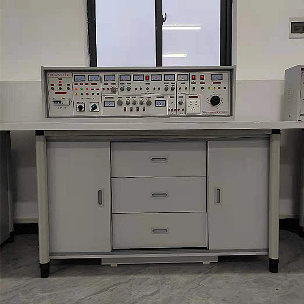
3. Experimental bench and operating table structure:
|
1. Experimental bench shell size: 123×35×20cm 2. Three phase fuse 3. Three-phase power input indicators 4. M*n switch: m*n switch of the power supply of the experimental bench, with leakage and overload protection 5. Test button: Test the leakage function of the leakage switch 6. Power input indicator 1 7. 3 power output indicators (red, green and yellow) 8. AC voltmeter: Indicates output line voltage 9. Voltage conversion switch: Used in conjunction with a voltmeter to monitor the size and symmetry of the output line voltage 10. 5 terminal blocks: unit A three-phase four-wire and ground wire output 11. Ammeter W phase current output indication 12. O/I switch: three-phase four-wire power output control (Improve safety factor) 13. 2 terminal blocks: Unit B AC low-voltage power output 14. Electric meter (2A): Unit B AC current indication 15. Knob: Unit B 3-24V AC low voltage selection output 16. Switch: C unit dual-channel DC regulated power supply switch 17. Knob: C unit dual-channel I channel steady flow adjustment 18. Knob: C unit dual-channel II channel steady flow adjustment 19. 2 terminal blocks: Unit C Ⅰ DC regulated output 20. Insurance holder: C unit dual-channel regulated power supply fuse twenty one. 4 electric meters: dual-channel regulated power supply voltage and current indication twenty two. Terminal block: D unit DC 5V regulated output twenty three. Electric meter: D unit current 0.5V output indication twenty four. Switch 1: Controls various low-voltage alternating current and signal sources 25. Switch 2: Control the AC and DC voltage-regulated power supply of unit E 26. Electric meter: E unit AC voltage output indication 27. 4 terminal blocks: E unit AC and DC output ports 28. Knob: E unit 0~240V voltage adjustment |
29. Socket: G unit 220V output socket 30. Knob: Audio power amplifier volume adjustment 31. 2 terminal blocks: audio signal input 32. Button: Single pulse enable switch 33. 3 terminal blocks: single pulse output port 34. Electric meter: function generator sine wave output voltage indication 35. Knob: coarse adjustment of three-level attenuation amplitude of sine wave output 36. Knob: Sine wave output port 37. Terminal block: sine wave output port 38. Knob: Rectangular wave output amplitude adjustment 39. Terminal block: triangle wave output port 40. Knob: Function signal generator frequency fine adjustment 41. Terminal block: rectangular wave output port 42. Knob: Function signal generator five-level frequency coarse adjustment 43. Electric meter: function generator output frequency indication 44. Multimeter: digital 45. Intelligent AC circuit measuring ammeter: It can measure circuit I, U, KW, Kwh, T at the same time through switch switching, eight-digit LCD display. 45. Experimental desktop size: 160×70cm 46. Universal circuit board: specification 35×90cm, component boxes can be assembled and inserted on it for experiments 47. Storage board: Place component boxes 48. Left storage cabinet: place storage board (with door lock) 49. Drawer: place commonly used tools 50. Right storage cabinet: place storage board (with door lock) 51. Oscilloscope: Prepare your own digital oscilloscope with 20M bandwidth 52. Millivolt meter: self-prepared |
4. M*n technical indicators of the experimental bench:
1. Input working power: three-phase four-wire
2. Output power and signal
Unit A: three-phase four-wire
Unit B: AC 3, 6, 9, 12, 15, 18, 24V
Unit C: Dual-channel constant-current regulated power supply (with overload and short-circuit protection functions), both output voltages are 0~30V, built-in relay automatically shifts gears, continuously adjusted by a multi-turn potentiometer, easy to use, outputs maximum current It is 2A and has preset current limiting protection function.
Voltage stability: <10-2 Load stability: <10-2 Ripple voltage: <5mv
Unit D: DC regulated voltage 5V, current 0.5A
Unit E: AC and DC voltage continuously adjustable from 0 to 240V, current 2A
Unit F: 220V voltage output for external instruments.
G: Virtual multimeter parameters:
AC voltage ranges: 10, 50, 250, 1000
DC voltage range points: 0.25, 1, 2.5, 10, 50, 250, 1000
Ohm scale: x1, x10, 100, 1000, 1K, x10K, x100K
Ammeter gears: 50μa, 0.5, 5, 50, 500
BATT: 1.2-3.6V, RL=12Ω
BUZZ:R×3
Infrared emission detection function: vertical angle ±15°, distance 1-30cm, triode measurement hole
3. Single pulse source: a p*r of positive and negative pulses can be output each time
4. Function signal generator (sine wave, triangle wave, rectangular wave)
① Frequency range: 5HZ-550KHZ is divided into five frequency bands
② Frequency indication: read directly from the HZ meter
③Voltage output range: sine wave: 5HZ-250KHZ>4.5V, 250KHZ-550KHZ>3.5V
Three levels of attenuation: 0db, 20db, 40db with continuous fine adjustment
Rectangular wave: 5HZ-250KHZ>4.5V, 250KHZ-550KHZ>3.5V, the amplitude is continuously adjustable
Triangular wave: 5HZ-550KHZ>1V
5. Audio power amplifier: The input audio voltage is not less than 10mv, the output power is not less than 1W, the volume is adjustable, and there is a speaker inside, which is used for amplifier circuit amplification and can also be used as a signal tracing instrument.
6. Intelligent multi-functional AC measuring meter: with an accuracy of level 1.0, it can simultaneously measure the circuit current I, voltage U, power Kw, electric energy Kwh and working time T. It has an eight-digit LCD display.
7. Insulation resistance: >5MΩ
8. Leakage protection: leakage action current ≤30mA
5. Structure, equipment and experimental projects
(1) Structure and equipment:
1. Experimental table: one with two seats, table dimensions: 160×70×80cm. A universal circuit board is placed in the center of the table. Each table is equipped with a rubber plate to protect the general circuit board and desktop (if motors , welding, etc. need to be placed on it ). Under the table are component storage cabinets for placing components.
2. Equipment and equipment:
Three-phase 180W motor, time relay, AC contactor, AC/DC ammeter, multimeter, indicator light, travel switch, control button, reverse switch, transformer, resistors, potentiometers, inductance coils, mutual inductance coils, diodes, transistors required for the experiment , FET, integrated, thyristor, logic level switch, logic level indicator and other component boxes (components have been installed in the component box), wire strippers, screwdrivers, needle nose pliers and other tools.
3. M*ntenance of electricians, electronic motors and vocational qualification tr*ning assessment simulation software
This software is in apk format and can be used on PC or mobile. This software can set faults manually or automatically. This software can manually set fault points through the green box in the circuit diagram (you can set up to 39 fault points), you can also automatically set one random fault point, two random fault points, three random fault points, four random fault points, and five random fault points through the system. It has functions such as toolbox, component library, magnifying glass, circuit diagram, etc. You can choose a multimeter for testing through the toolbox, select appropriate components through the component library, and clearly understand each component and circuit through the magnifying glass. This software allows students to understand the working principle and circuit structure of the motor star-delta start control circuit through the setting of faults in the motor star-delta start control circuit and various investigations.
4. Virtual spectrum analyzer, logic analyzer, oscilloscope, and three-meter simulation software
This software is in apk format and can be used on PC or mobile terminals. The functions of this software are: resistance measurement, AC voltage measurement (measuring transformer, if the multimeter burns out when measuring the transformer, black smoke will emit prompts and can reset the multimeter), determine the polarity of the transistor, measure the DC voltage (the light turns on when the ammeter is turned on), measure the DC current, and determine the quality of the capacitor. This software can drag the red and black pen tips at will. When the two pen tips are dragged and positioned on the object to be measured, a red circle will be displayed. If the positioning is not accurate, no red circle will be displayed, and when incorrect operations are performed (such as the wrong range selected, If the measured data is wrong, etc.), the meter pointer will not respond, prompting errors and re-measurement, etc. This multimeter can select AC voltage gear, DC voltage gear, resistance gear, current gear, resistance adjustment to 0, and can enlarge the display data. Clearly view the measured data size. Students can learn the correct use of multimeters through this software.
5. Mechanical tr*ning safety education virtual simulation software
This software is developed based on unity3d. The software adopts the form of three-dimensional roaming. Movement can be controlled by the keyboard and the lens direction can be controlled by the mouse. It has mechanical safety distance experiments, mechanical safety protection device experiments, and basic assessment of mechanical safety protection design. During the experiment, the three-dimensional roaming The screen uses arrows and footprints to prompt you to move to the experimental location. The circle around the mechanical object shows the working radius. The experimental process is accompanied by a dialog box reminder of the three-dimensional robot. The content is as follows:
A. The content of the mechanical safety distance experiment includes the safety distance experiment to prevent upper and lower limbs from touching the danger zone (divided into two fence heights and opening sizes). After selecting to enter, GB23821-2009 "Mechanical Safety to Prevent Upper and Lower Limbs from Touching the Danger Zone" pops up in front of the camera. "Safe Distance" requirements, error demonstration: The experimental process is that after the human body enters the working radius of the mechanical object and is injured, the red screen and voice prompts that the human body has received mechanical damage, and returns to the original position and conducts the next experiment. The last step is the correct approach.
B. Mechanical safety protection device experiments are divided into safety interlock switches, safety light curt*ns, safety mats, safety laser scanners and other protection device experiments. Optional categories (safety input, safety control, safety output, others), manufacturers, products List (safety interlock switch, safety light curt*n, safety mat, safety laser scanner, safety controller, safety relay, safety guardr*l). There is a blue flashing frame reminder at the installation location. Experimental process: select the safety guardr*l and install it, select the safety interlock switch (or select the safety light curt*n, safety mat, safety laser scanner) and install it, select the safety controller and install it in the electrical control box , select the safety relay and install it in the electrical control box, click the start button on the electrical control box. If you enter a dangerous area, the system will sound an alarm and the mechanical object will stop working. Select the reset button on the electrical control box to stop.
C. The basic assessment of mechanical safety protection design requires the completion of the installation of the mechanical safety system, and the correct installation of safety guardr*ls, safety interlock switches, safety light curt*ns, safety mats, safety laser scanners, safety controllers, safety relays, 24V power supplies, signal lights and Emergency stop button, the assessment is divided into ten assessment points. Some assessment points have 3 options, which are freely chosen by the students. After selecting the final 10 assessment points, submit for confirmation, and the system will automatically obt*n the total score and the score of each assessment point. .
D. The software must be on the same platform as a whole and must not be displayed as separate resources.
E. At the same time, we provide customers with the VR installation package of this software to facilitate users to expand into VR experiments. VR equipment and software installation and debugging are not required.
(2) Experimental projects:
(1) Electrical experimental project
|
1. Use of electrical measuring instruments 2. Identification and detection of commonly used components 3. Volt-ampere characteristics of linear components and nonlinear components 4. External characteristics of power supply 5. Measurement of potential value and voltage value 6. Range extension for ammeters and voltmeters 7. Verification of Kirchhoff's Laws 8. Verification of Lenz's law 9. Verification of the superposition principle and reciprocity theorem 10. Verification of Thevenin's Theorem and Norton's Theorem 11. Equivalent transformation of voltage source and current source 12. Research on controlled source characteristics 13. First order circuit experiment 14. Transition process of second-order circuit 15. Study the characteristics of LC components in DC and AC circuits 16. Conditions for the load to obt*n maximum power |
17. Measurement of AC circuit parameters 18. Characteristics of RLC components in sinusoidal AC circuits 19. RL and RC series circuit experiments 20. RLC series resonant circuit twenty one. Fluorescent lamp circuit connection and power factor improvement twenty two. Star and delta connection of three-phase load twenty three. Three-phase circuit and power measurement twenty four. Research on RC Frequency Selective Network 25. Two-port network research 26. Single phase transformer experiment 27. Mutual inductance circuit experiment 28. Use and starting of three-phase asynchronous motor 29. Basic circuit of three-phase motor relay contact control 30. Three-phase motor Y-△ starting control experiment 31. Sequential control experiment of three-phase motor 32. Three-phase motor energy consumption braking control experiment |
The following circuit experiments can also be completed using the components of the above 32 experiments.
|
33. The simplest circuit 34. Selection of potentials and reference points at each point in the circuit 35. series connection of resistors 36. Resistors in parallel 37. Mixed connection of resistors 38. resistor divider circuit 39. Ohm's law for the whole circuit 40. Bridge application and balancing conditions 41. node voltage method 42. loop voltage method 43. branch current method 44. RCL parallel circuit 45. series circuit 46. Transformer structure and working principle 47. Kirchhoff's first law 48. Kirchhoff's second law 49. Fluorescent lamp circuit principle 50. Expand the voltmeter range 51. Expand ammeter range 52. Transition process of RC circuit 53. RL transition process 54. series circuit of capacitors 55. capacitor parallel circuit |
56. Capacitor charging and discharging 57. The role of capacitors in AC and DC 58. Movement of bar magnet in coil 59. Mixed connection of capacitors 60. Pure resistance, inductance, capacitance circuits 61. Magnetic coupling coil sequence 62. Counter-series of magnetically coupled coils 63. How an ohmmeter works 64. Double switch two ground control 65. Use an oscilloscope to observe the hysteresis loop 66. Magnetic Circuit Ohm's Law 67. The mutual inductance of the two coils and the same terminal 68. mutual inductance coupling 69. How to improve power factor 70. Measurement of single-phase circuit power 71. Radio recorder power circuit 72. filter circuit 73. The relationship between resistance and temperature: measuring the filament using voltammetry resistance at different voltages. 74. Three-phase asynchronous motor knife control forward rotation experiment 75. Control circuit with overload protection 76. Button controlled forward and reverse control circuit 77. Contactor control star-delta step-down starting control circuit |
(2) Electronic experiment project
|
1. Characteristics and detection of crystal diodes 2. Transistor input and output characteristics 3. Low frequency small signal voltage amplifier 4. Directly coupled two-stage amplifier 5. RC coupled two-stage amplifier 6. The impact of negative feedback on amplifier performance 7. Transformer coupled push-pull power amplifier 8. Complementary Symmetrical Push-Pull Power Amplifier (OTL) 9. Single phase half wave rectifier 10. Single phase full wave rectification 11. Single phase bridge rectifier 12. Single-phase bridge rectifier filter 13. Single junction transistor characteristics 14. Unijunction transistor trigger circuit 15. Simple test of thyristor and controllable rectifier circuit 16. Field effect tube test 17. Series regulated voltage 18. Research on differential amplifier circuit 19. Testing of integrated operational amplifier parameters 20. Integrated op amp subtraction circuit twenty one. Integrated op amp adding circuit twenty two. Integrated operational amplifier integrating circuit |
twenty three. Integrated operational amplifier differential circuit twenty four. Integrated Op Amp Wien Sine Wave Oscillator 25. Capacitive three-point oscillator 26. Inductive three-point oscillator 27. Integrated voltage stabilizing circuit 28. Astable circuits (multivibrators) 29. Schmitt trigger 30. Integrated AND gate logic function test 31. Integrated NOT gate logic function test 32. Integrated OR gate logic function test 33. Integrated NAND gate logic function test 34. Testing of CMOS gate circuits 35. Basic RS flip-flop 36. JK flip-flop 37. D flip-flop 38. Application of 555 time base circuit (square wave generator) 39. binary decimal counter 40. Binary decimal 8421 decoder 41. Adder 42. subtractor 43. Constructing a Monostable Flip-Flop Using Integrated NAND Gates 44. combinational logic circuit |
|
45. PN junction unidirectional conductive characteristics 46. Measurement circuit of three-power ICBO 47. Measurement circuit of triode ICEO 48. Transistor current amplification 49. VA characteristics of triode 50. Single-stage small-signal voltage amplification with load 51. Voltage negative feedback bias circuit 52. Voltage-divided current negative feedback bias circuit 53. Stabilizing the operating point with a thermistor 54. Using diodes to stabilize the operating point 55. Analyze the influence of Ce on low frequency characteristics 56. Common base amplifier experimental circuit 57. Common collector amplification experimental circuit 58. Common source basic amplifier circuit 59. Field effect tube self-cont*ned bias amplifier circuit 60. Field effect transistor voltage dividing self-bias circuit 61. Field effect transistor common dr*n circuit 62. Field effect transistor common gate circuit 63. Single-tube resistance-capacitance amplifier circuit 64. Basic DC amplifier circuit 65. Use a resistor to increase the emitter potential of the subsequent stage 66. Use a voltage regulator tube to increase the emitter potential of the rear stage 67. Transformer coupled amplifier circuit 68. Class A power amplifier circuit 69. Class B power amplifier circuit 70. Series current negative feedback 71. Series voltage negative feedback circuit 72. Parallel voltage negative feedback circuit 73. Parallel current negative feedback circuit 74. Negative feedback in two-stage amplifier circuit 75. Emitter output circuit 76. Bootstrap emitter output circuit 77. Use capacitors to attenuate high-frequency voltages 78. Use negative feedback to eliminate self-oscillation 79. battery monitoring circuit 80. Field effect transistors and transistors form an amplifier circuit 81. PNP-NPN direct coupling amplifier circuit 82. Common base cascode amplifier circuit 83. Transistor switching function 84. Liquid level photoelectric control 85. Simple temperature control circuit 86. Analog light-controlled simple street light automatic switch circuit 87. RC Phase Shift Oscillator 88. Double T frequency selection network 89. Oscillator composed of double T frequency selective network 90. Transformer feedback oscillation circuit 91. Field effect transistor transformer feedback oscillation circuit 92. Anti-theft alarm circuit 93. Series crystal oscillator circuit 94. complementary audio oscillator 95. alarm sounder 96. Music doorbell circuit 97. Electronic alarm circuit 98. The basic form of differential amplifier circuit 99. Electronic doorbell circuit 100. Quasi-complementary symmetrical circuit 101. Three-tube OTL complementary symmetrical circuit 102. Long t*l differential amplifier circuit 103. Differential input single-ended output 104. Single-ended input double-ended output 105. Single-ended input single-ended output 106. Dual power supply long t*l differential amplifier circuit 107. Differential amplifier experimental circuit 108. Differential amplifier circuit measures with constant current source 109. Ironic analysis of single-ended output differential amplifier circuit 110. flasher circuit 111. Basic connection method of operational amplifier 112. Current differential operational amplifier is used as AC proportional amplification 113. Simple measurement method of Vos 114. A simple measurement method for Aos 115. A simple measurement method of Aod 116. Simple test of common mode rejection ratio Cmrr 117. Simple test of maximum common mode input voltage UIcm 118. Yopp's simple test 119. SR measurement method 120. Basic non-inverting amplification connection method 121. LC oscillator composed of op amp 122. Electric heating cup temperature adjustment circuit 123. Lead to the reverse end input zero adjustment measure 124. Lead to the same direction end and input the zero adjustment instruction. 125. In order to prevent the electric value from being too large, 126. Using the base current of the transistor to achieve temperature compensation for Ios 127. Utilizing T-shaped network to improve equivalent feedback resistance 128. Measures to make the complementary tube work in Category A and B to expand the output current 129. Measures to be taken when correcting capacitive loads 130. Inverting input protection measures 131. Non-inverting input protection measures 132. Use voltage regulator tubes to protect devices 133. Protection ag*nst wrong polarity of power supply 134. Instantaneous overvoltage protection when power is on 135. Diode detection circuit 136. Circuit principle of measuring temperature using the temperature coefficient of PN junction 137. Dual diode limiter 138. Basic circuit of inverting op amp 139. Variable ratio magnification 140. Basic circuit of non-inverting op amp 141. Voltage/current conversion circuit 142. Current/voltage conversion circuit 143. voltage follower |
144. Differential amplifier basic circuit 145. The differential output of the operational amplifier 146. Inverted input sum operation 147. In-phase input summation operation 148. Two-ended input sum operation 149. Basic integrating circuit 150. EG test leakage resistance p*r integral operation circuit 151. Measures to improve the integration time constant 152. Fast integrating circuit 153. Simulate first-order differential equation circuits 154. Simulate second-order differential equation circuits 155. basic differential circuit 156. Practical Differential Circuits 157. Using indirect methods to obt*n approximate differentials 158. Basic logarithmic operation circuit 159. Using the logarithmic characteristics of transistors to form a logarithmic operation circuit 160. Basic circuit of antilog amplification 161. Vo is proportional to the VxVy circuit 162. Simple zero-crossing comparison circuit 163. Comparator circuit with hysteresis characteristics 164. Double limit comparison circuit 165. Using diodes as upper limit detection amplitude selection circuit 166. Double limit three-state comparison circuit 167. Lower limit detection amplitude selection circuit 168. Basic sampling protection circuit 169. RC passive network terminal low-pass filter circuit 170. The filter circuit is connected to the non-inverting input terminal of the component 171. The filter circuit is connected to the inverting input of the component 172. Simple second-order RC filter circuit 173. Typical RC active filter circuit 174. Two-stage active filter circuit 175. Multi-channel feedback secondary active filter circuit 176. Typical second-order high-pass active filter circuit 177. Basic bandpass filter circuit 178. Typical bandpass filter circuit 179. Band stop filter composed of double T network 180. Output limiting inverter 181. Practical Difference Op Amp 182. Square wave oscillator circuit 183. Resistor-capacitor phase shift trigger circuit 184. Electric heating mattress temperature control device 185. Adjustable width rectangular wave generator 186. Simple sawtooth wave generator 187. Amplitude and frequency adjustable sawtooth wave generator 188. Commonly used drawing circuits for single-phase bridge rectifiers 189. Maximum reverse peak voltage of full-wave rectifier circuit 190. Capacitor filter circuit 191. Capacitive filter with resistive load 192. Full wave rectifier capacitor filter circuit 193. RC filter circuit 194. Multi-stage RC filter circuit 195. Basic LC filter circuit 196. T-shaped filter circuit 197. Double voltage rectifier circuit 198. Triple voltage rectifier circuit 199. Basic voltage regulator circuit 200. Basic regulating tube voltage stabilizing circuit 201. Voltage stabilizing circuit with amplification link 202. Adjustment tube current stabilizing circuit 203. electronic filter 204. Series voltage stabilizing circuit 205. Parallel voltage stabilizing circuit 206. electronic hypnosis device 207. Three-terminal integrated voltage stabilizing circuit 208. Positive power output adjustable integrated voltage stabilizing circuit 209. Single-phase full-wave controllable rectification 210. Silicon voltage regulator circuit 211. Single-phase half-wave controllable rectification 212. Single-phase bridge semi-controlled rectifier 213. Principle of silicon rectifier for charging 214. Effect of inductive load on thyristor 215. Thyristor trigger conduction test 216. Back electromotive force load thyristor circuit 217. Simple electronic voltage regulation circuit 218. Test the single-junction tube partial pressure ratio n 219. Single junction oscillator circuit 220. Single junction tube trigger application circuit 221. Diode AND gate circuit 222. Transistor "OR" gate circuit 223. visualization with logic 224. or logical visualization 225. illogical visualization 226. Transistor "NOT" Gate 227. Transistor NAND gate 228. Transistor "NOR" gate 229. Three-barrel bistable circuit 330. triode monostable circuit 231. triode multivibrator circuit 232. Set trigger circuit 233. emitter coupled bistable 234. Symmetric multivibrator 235. ring multivibrator 236. Differential monostable circuit 237. Integrated Schmitt circuit 238. Square wave generator 239. single pulse circuit 240. continuous pulse generator |
(3) Electrical control part experiment
|
1. Knife switch forward control circuit 2. Contactor inching forward control circuit 3. Forward rotation control circuit with self-locking 4. Forward rotation control circuit with over-finding protection 5. Reverse switch controls forward and reverse control circuits 6. Contactor interlocking forward and reverse control circuit 7. Button interlocking forward and reverse control circuit 8. Button contactor composite interlock control circuit 9. Automatic round trip control circuit 10. Contactor controlled series resistor step-down starting line 11. Time relay controls series resistor voltage reduction control circuit 12. Manual Y/△ reduced voltage start 13. Contactor control Y/△ reduced voltage starting 14. Time relay controls Y/△ step-down starting |
15. QX3-13 type Y/△ automatic starting control circuit 16. Half-wave rectification energy consumption braking control circuit 17. Full-wave rectification energy consumption braking control circuit 18. C620 lathe electrical control circuit 19. Manual step-down starting 20. Single-phase operation reverse braking control circuit twenty one. Electric hoist electrical control circuit twenty two. C6163 lathe electrical control circuit twenty three. Control circuit interlock control circuit twenty four. M*n circuit interlock control circuit |
 Wechat scan code follow us

24-hour hotline+86 18916464525

Phone18916464525
ADD:Factory 414, District A, No. 6, Chongnan Road, Songjiang Science and Technology Park, Shanghai ICP: Sitemap