Shanghai Daiyu Education Equipment Manufacturing Co., Ltd.
Language:


This device is developed in accordance with the "Programmable Control System Designer" tr*ning and the national occupational standard assessment syllabus formulated by the Ministry of Human Resources and Social Security, with appropriate additions of new technologies, and in accordance with the requirements of vocational education and tr*ning, vocational skills appr*sal and practical tr*ning teaching of. It is suitable for vocational colleges, vocational tr*ning schools, vocational education centers, appr*sal stations/institutes to carry out tr*ning and skill appr*sal for fourth, third and second level programmable control system designers.
2. R&D background
1. This device is based on the "Programmable Control System Designer" tr*ning and the national occupational standard assessment syllabus formulated by the Ministry of Human Resources and Social Security, with appropriate additions of new technologies, and in accordance with the requirements of vocational education and tr*ning, vocational skills appr*sal and practical tr*ning teaching And developed.
2. With the rapid development of industry, processor requirements are constantly increasing, and teaching needs to keep pace with the times. Equipment must be continuously upgraded, and teaching needs to start from the basics. At the same time, to meet the needs, duplication of laboratory construction will lead to a waste of money and laboratory space.
3. A product requires multiple processing techniques, resulting in complex industrial field equipment. One host cannot complete all the work, and multiple sites need to cooperate with each other to complete the work.
4. Assessments at different levels require different equipment and cannot be combined organically. Some practical tr*ning cannot be considered to check students’ acceptance after completion.
3. Product Features
1. The construction concept of practical tr*ning is one-time construction. This equipment adopts a universal wide expansion port. All the I/O ports of the host can be led out through the expansion port. It can be used for plug-in tr*ning and wire-connected practical operations. tr*ning; there are also two removable mesh boards to assess students at different levels.
2. It adopts a modular modular structure, including switching values, analog values, frequency conversion speed regulation, touch screen, communication modules, etc., and is equipped with MCGS industrial control configuration monitoring software to realize simulation and information-based practical tr*ning and teaching.
3. Project tr*ning module: Use current typical programmable controllers and bus technologies to complete the control of logic, simulation, process, motion, etc. in simulated objects and physical models of typical cases in industrial production.
4. Simulation tr*ning and teaching: The virtual environment displays the PLC operating status in real time, simulates industrial on-site control, and can perform programming tr*ning, program writing testing and other functions.
4. Technical performance
1. Input power supply: three-phase four-wire (or three-phase five-wire) AC380V±10% 50Hz
2. Device capacity: <0.5kVA
3. Weight: 100kg
4. Overall dimensions: 1310mm×700mm×1780mm
5. Safety protection: It has leakage voltage and leakage current protection devices, and is safe and in line with national standards.
6. 6. Virtual multimeter parameters:
AC voltage ranges: 10, 50, 250, 1000
DC voltage range points: 0.25, 1, 2.5, 10, 50, 250, 1000
Ohm scale: x1, x10, 100, 1000, 1K, x10K, x100K
Ammeter gears: 50μa, 0.5, 5, 50, 500
BATT: 1.2-3.6V, RL=12Ω
BUZZ:R×3
Infrared emission detection function: vertical angle ±15°, distance 1-30cm
Transistor measuring hole
5. Basic configuration and functions
The tr*ning device consists of a tr*ning platform, power module, PLC simulation control module, S7-1200 unit, frequency conversion speed regulation unit, touch screen unit, two-dimensional control unit, basic electrician tr*ning unit, AC motor , profile computer desk and experimental wires, etc. composition. The relevant electrical component interfaces are drawn out through multi-functional terminals, with two methods: jack-type experimental verification and wiring-type engineering tr*ning. Students can independently build relevant electrical control circuits.
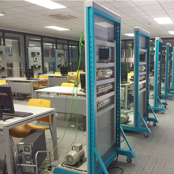
1. Practical tr*ning platform
The platform adopts a vertical mesh plate structure, which is made of industrial aluminum profiles. The mesh plate on the left is a fixed structure; on the right are two detachable mesh plates. There are universal wheels with brakes at the bottom for easy movement. The layout and shape are beautiful and elegant.
2. Power module
Provides three-phase 380V AC power supply and single-phase 220V AC power supply. The AC power output is equipped with an intelligent equipment control and safety protection system, which can automatically protect ag*nst overcurrent and direct short circuit between phases and lines. And provide DC 24V/5A power supply.
3. PLC simulation control module
After students write the control program in the standard PLC programming environment, they compile and download it to the PLC for practical tr*ning to achieve real-time control of the virtual scene. The hanging box focuses on learning PLC application simulation control programming tr*ning, and uses a pistol plug-in sheath structure tr*ning connection line to build a tr*ning circuit.
It can complete digital display control, answering machine control, sky tower light control, musical fount*n control, intersection traffic light control, water tower water level control, automatic feeding and loading system control, four-section conveyor belt control, assembly line control, and various liquid mixing Practical tr*ning projects include device control, automatic forming machine control, automatic rolling mill control, m*l sorting machine control, vending machine control, robot control, four-story elevator control, machining center control, automatic washing machine, electroplating production line, etc.
4. S7-1200 unit
Host 1215C, working memory 125 KB; working power supply 24VDC, built-in DI14/DQ10, AI2/AQ2 onboard DI14 x 24VDC sink/source type, onboard DQ10 x 24VDC and AI2 and AQ2; onboard 6 high-speed counters and 4 pulse output; supports 3 communication modules for serial communication and 8 signal modules for I/O expansion; runs at 0.04 ms/1000 instructions; has 2 PROFINET ports for programming, HMI and PLC data communication between.
Multi-functional terminals, the electrical interface is derived from multi-functional terminals, and has two methods: jack-type experimental verification and wiring-type engineering tr*ning. Students can independently build relevant electrical control circuits.
5. Touch screen unit
The touch screen unit adopts Siemens KTP700 Basic 7-inch color touch screen, which is used for Ethernet communication with the PLC host to control and display the operating status of each unit. Equipped with genuine Siemens software WinCC.
6. Frequency conversion speed regulating unit
Provide a Siemens inverter G120C with a power of 0.37KW and a voltage of 380V. It supports 6 digital inputs, 4 outputs, and two analog inputs and outputs.
7. Car motion control unit
It is m*nly composed of a sports car (driven by a DC motor), a synchronous pulley transmission mechanism, a DC motor, a photoelectric sensor , an inductive sensor, a capacitive sensor, a travel switch, etc. It realizes transmission control and key value optimization through sensor detection and PLC programming. Compare walking control, directional control, positioning control, alarm operation control, inching control, etc., to achieve precise positioning of the car. The system looks great, is compact and lightweight.
8. Two-dimensional control unit
The two-dimensional control unit is m*nly composed of servo drive and stepper drive.
The servo drive is used to control the Y-axis screw rod, using Siemens V90 AC servo drive and motor, with an operating voltage of AC220V and an output power of 400W. Using a digital signal processor (DSP) as the control core, the intelligent power module (IPM) integrates a drive circuit and has fault detection and protection circuits such as overvoltage, overcurrent, overheating, and undervoltage. It has strong temperature, humidity, It has the ability to adapt to vibration and other environments and has strong anti-interference ability; it supports position, speed and torque to control the servo motor.
The stepper drive is used to control the X-axis screw rod, using DC servo drive, operating voltage DC24V, output power 35W; internal integrated control circuit and power circuit, with self-check coil and short-circuit protection functions.
(4) Multi-functional terminals. The electrical interface is drawn from multi-functional terminals. It has two methods: jack-type experimental verification and wiring-type engineering tr*ning. Students can independently build relevant electrical control circuits.
9. Basic electrician tr*ning unit
|
serial number |
name |
Models and Specifications |
quantity |
|
1 |
Low voltage circuit breaker |
DZ108-20 10A |
1 |
|
2 |
screw type fuse |
RL1-15/3A |
3 |
|
3 |
Push-in fuse |
RT14-20/2A |
2 |
|
4 |
AC contactor |
CJX2-0910, AC220V |
3 |
|
5 |
Auxiliary contacts |
F4-22 |
2 |
|
6 |
thermal relay |
JRS1D-25/Z(0.63-1A) |
1 |
|
7 |
Thermal relay base |
JRS1-25 |
1 |
|
8 |
Power on delay time relay |
JSZ6-4/220V(0~60S) |
1 |
|
9 |
Time relay base |
JSZ6-4 |
1 |
|
10 |
Intermediate relay |
ARM2F-L/DC24V with light |
3 |
|
11 |
Relay base |
DYF-08A |
3 |
|
12 |
Terminal block |
JF5-2.5/5 |
5 |
|
13 |
Limit switch |
LX19-001 |
2 |
|
14 |
G terminal r*l |
2 sticks |
|
|
15 |
button switch box |
Equipped with three button switches: yellow, green and red |
1 set |
|
16 |
button switch box |
Equipped with two green and red push button switches |
1 set |
|
17 |
wire |
1 roll each of red/black |
2 volumes |
|
18 |
trunking |
25*25 |
5 meters |
10. Three-phase AC motor
AC rated voltage 380V/△ connection method, rotation speed 1400 rpm, power 40W, frequency 50HZ, insulation grade E.
11. Profile computer desk
Computer desks use aluminum profiles and sheet metal structures to place computers. The countertop is made of fireproof, waterproof and wear-resistant high-density board; the columns and beams are made of 30×30 industrial aluminum alloy profiles. The keyboard is a drawer-type structure and fixed with 300mm guide r*ls; the bottom of the computer desk is equipped with a universal wheel with brakes. The size is approximately 560mm×600mm×1020mm.
12. Experimental cable
Each set is equipped with a high-reliability sheathed structure pistol plug connection line, which is made of oxygen-free copper wire drawing. The plug is made of solid copper parts coated with beryllium light copper shrapnel. The plug and socket sizes of strong and weak current conductors are separated and cannot be mixed. It is safe. reliable.
13. Microcontroller and PLC programmable design and control virtual simulation software:
This software is developed based on unity3d and has built-in experimental steps, experimental instructions, circuit diagrams, component lists, connection lines, power on, circuit diagrams, scene reset, return and other buttons. After the connections and codes are correct, you can start/stop, The forward movement and reverse movement buttons operate the 3D machine tool model to move. In the connected line state, the 3D machine tool model can be enlarged/reduced and translated.
1. Relay control: Read the experiment instructions and enter the experiment. By reading the circuit diagram, select the relays, thermal relays, switches and other components in the component list and drag and drop them into the electrical cabinet. The limiters are placed in the three-dimensional On the machine tool model, you can choose to cover it, and some component names can be renamed. Then click the Connect Line button to connect terminals to terminals. After successfully connecting the machine tool circuit, choose to turn on the power and proceed. If the component or line An error box will pop up if there is a connection error, and the scene can be reset at any time.
2. PLC control: The experiment is the same as relay control, with the addition of PLC control function. After the connection is completed, enter the program writing interface through the PLC coding button, and write two programs, forward and reverse, with a total of 12 ladder diagram symbols. The writing is completed. Finally, select Submit for program verification. After the verification is successful, turn on the power for operation. Error boxes will pop up for component, line connection, and code errors, and the scene can be reset at any time.
3. Single-chip microcomputer control: The experiment is the same as relay control, with the addition of single-chip microcomputer control function. After the connection is completed, enter the programming interface through the C coding button, enter the correct C language code, and after successful submission and verification, turn on the power for operation, components, lines If there are connection or code errors, an error box will pop up, and the scene can be reset at any time.
6. Practical tr*ning projects
PLC basic skills tr*ning
MCGS configuration bar chart experimental teaching uses the edited configuration bar chart to dynamically track any of the following experiments. According to the specific requirements of the experimental project, students edit the configuration bar chart themselves to conduct experiments.
1. PLC cognitive tr*ning (software and hardware structure, system composition, basic instructions, wiring, programming download, etc.)
PLC virtual control application tr*ning
2. Digital display control
3. Answerer control
4. Sky Tower Light Control
5. Music fount*n control
6. Crossroad traffic light control
7. Water tower water level control
8. Automatic feeding and loading system control
9. Four-section conveyor belt control
10. Assembly line control
11. Multiple liquid mixing device control
12. Automatic molding machine control
13. Automatic washing machine control
14. Electroplating production line control
15. Automatic rolling mill control
16. M*l sorting machine control
17. Vending machine control
18. Robot control
19. Four-story elevator control
PLC physical control application tr*ning
20. Stepper motor positioning control
21. Speed control of stepper motor
22. Forward and reverse control of stepper motor
23. Servo motor positioning control
24. Speed control of servo motor
25. Forward and reverse control of servo motor
26. Comprehensive control of servo motors and stepper motors
Typical motor control practical tr*ning
27. Three-phase squirrel cage asynchronous motor inching and self-locking PLC control
28. Three-phase squirrel cage asynchronous motor linked forward and reverse PLC control
29. Three-phase squirrel-cage asynchronous motor with delayed forward and reverse PLC control
30. Three-phase squirrel-cage asynchronous motor Y/△ conversion starting PLC control
PLC, frequency converter, touch screen comprehensive application skills tr*ning
31. Frequency converter function parameter setting and operation
32. External terminal jog control
33. Frequency converter controls motor forward and reverse rotation
34. Multi-stage speed selection and frequency conversion speed regulation
35. Inverter stepless speed regulation
36. Frequency conversion speed control using external analog quantity method
37. Motor forward and reverse control based on PLC external terminals of the frequency converter
38. Frequency conversion open-loop speed control based on PLC analog method
39. Frequency conversion open-loop speed regulation based on PLC communication method
40. Basic command programming exercises based on touch screen control
41. Digital display control based on touch screen control method
Hot-selling product: Electrician tr*ning bench
 Wechat scan code follow us

24-hour hotline+86 18916464525

Phone18916464525
ADD:Factory 414, District A, No. 6, Chongnan Road, Songjiang Science and Technology Park, Shanghai ICP: Sitemap