Shanghai Daiyu Education Equipment Manufacturing Co., Ltd.
Language:


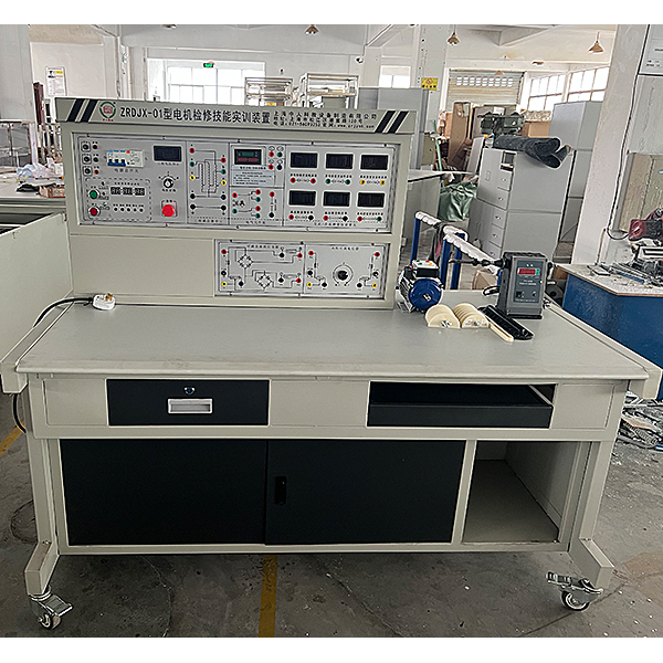


1. Motor m*ntenance skills tr*ning device Features of this tr*ning device
1. The control panel adopts a tr*ning platform structure, and the measuring instruments and electrical circuit components are fixed on the corresponding functional block panel.
2. The practical tr*ning projects are clearly classified and are specific to each step in the motor m*ntenance process, so that students can truly master the professional skills of motor m*ntenance.
3. The practical tr*ning device adopts a modular approach for skill tr*ning and deepening of theoretical knowledge.
4. This device has a good self-protection system and provides excellent tr*ning equipment for the realization of an open tr*ning room.
2. Motor m*ntenance skills tr*ning device Technical performance of this tr*ning device
1. Input voltage: three-phase four-wire (or three-phase five-wire) ~ 380V ± 10% 50Hz
2. Working environment: ambient temperature range is -10 ~ +40℃ Relative temperature <85% (25℃)
3. Device capacity: <1.5KVA
4. Weight: 100kg
3. Motor m*ntenance skills tr*ning device This tr*ning device is equipped with
1. Power control screen
The control panel is made of iron with a double-layer matt dense spray-p*nted structure and an aluminum panel.
2. Tr*ning table
The tr*ning table is made of iron and is equipped with an anti-static insulating rubber pad to protect the operating table.
3. M*n control function board equipment items
(1) Three-phase four-wire power input, through the leakage protector and m*n switch, is operated by the contactor through the start and stop buttons, and is equipped with an emergency stop control button.
(2) There are three pointer AC voltmeters on the control panel, which are used to monitor the line voltage between each two phases of the three-phase input power supply.
(3) Timer and alarm recorder (service manager), usually used as a clock, with functions such as setting time, timing alarms, cutting off power, etc.; it can also automatically record leakage alarms and instrument overruns caused by wiring or operation errors. The total number of range alarms provides a unified assessment standard for the assessment of students' skill tr*ning.
(4) Three-phase adjustable AC power supply, the voltage is regulated through a 1.5KVA three-phase auto-coupling voltage regulator, and the output is 0~450V/5A.
(5) DC power supply part:
A set of 220V/0.5A DC power supply with short circuit protection function.
A set of 0~250V adjustable DC high voltage power supply with overvoltage protection and short circuit protection functions.
4. Instruments
(1) Provide a true effective value AC digital voltmeter with a measuring range of 0~500V, automatic range judgment and automatic switching, an accuracy of 0.5 level, and a three-and-a-half-digit display.
(2) Three true effective value AC digital ammeters are provided, with a measuring range of 0~5A, automatic range judgment and automatic switching, an accuracy of 0.5 level, and a three-and-a-half-digit display.
(3) A DC digital milliamp meter: measuring range 0~2000mA, three and a half digit display, accuracy level 0.5.
(4) Provide a DC digital voltmeter with a measuring range of 0~300V, three levels of 2V, 20V and 300V, direct key switch, three-and-a-half-digit display, input impedance of 10MΩ, accuracy of 0.5 level, and over-range alarm. , indication and other functions, it can directly measure the DC armature power supply voltage and external voltage.
(5) An intelligent power and power factor meter: composed of a set of microcomputers, high-speed, high-precision A/D conversion chips and full digital display circuits. The intelligent control mode of human-machine dialogue is realized through key control and digital display window. In order to improve the measurement range and test accuracy, the sampling signals of the measured voltage and current instantaneous values are converted by A/D, and advanced DSP technology is used to calculate the active power and reactive power. The power meter accuracy is 0.5 level, and the voltage and current ranges are respectively It is 450V, 5A, and can measure the active power, reactive power, power factor and load properties of the load; it can also store and record 15 groups of power and power factor test result data, and can query group by group.
(6) Adjustable resistor: two sets of 0~900Ω/0.5A adjustable resistors.
Single-phase capacitor run motor capacitor: 4uF/450V CBB capacitor.
(7) Low-voltage electrical appliances: 3 fuses, 2 AC contactors, 1 thermal relay, etc.
(8) Teaching software
1. Electrical safety and electric shock first *d simulation teaching software
The software uses a combination of two-dimensional and three-dimensional virtual images to teach students the safety and first *d methods of using electricity. The software includes single-phase electric shock, two-phase electric shock, step electric shock, low-voltage electric shock first *d, high-voltage electric shock first *d, artificial respiration first *d, Principles of hand-holding breathing rescue method, chest cardiac compression and other protective methods are expl*ned and taught. Principles of single-phase electric shock are divided into rep*ring live disconnection, rep*ring socket electric shock, and outdoor electric shock. The teaching of low-voltage electric shock and high-voltage electric shock m*nly expl*ns and demonstrates to students how to rescue people who are suffering from low-voltage electric shock or high-voltage electric shock. Artificial respiration rescue method, hand-holding breathing rescue method, and chest cardiac compression rescue method are demonstrated using 3D virtual simulation technology. After rendering and Polish it to make the model look like the real part and look realistic. Through practical tr*ning, students can be educated on the safe use of electricity in the tr*ning room, improve students' safety awareness, and enable students to learn some self-rescue methods, so that students can take cert*n safety measures to protect themselves when encountering danger, and become familiar with various Causes of electrical accidents and practical measures to deal with them to reduce the occurrence of electrical accidents.
2. M*ntenance of electricians , electronic motors and vocational qualification tr*ning assessment simulation software
This software is in apk format and can be used on PC or mobile. This software can set faults manually or automatically. This software can manually set fault points through the green box in the circuit diagram (you can set up to 39 fault points), you can also automatically set one random fault point, two random fault points, three random fault points, four random fault points, and five random fault points through the system. It has functions such as toolbox, component library, magnifying glass, circuit diagram, etc. You can choose a multimeter for testing through the toolbox, select appropriate components through the component library, and clearly understand each component and circuit through the magnifying glass. This software allows students to understand the working principle and circuit structure of the motor star-delta start control circuit through the setting of faults in the motor star-delta start control circuit and various investigations.
3. Virtual spectrum analyzer, logic analyzer, oscilloscope, and three-meter simulation software:
This software is in apk format and can be used on PC or mobile terminals. The functions of this software are: resistance measurement, AC voltage measurement (measuring transformer, if the multimeter burns out when measuring the transformer, black smoke will emit prompts and can reset the multimeter), determine the polarity of the transistor, measure the DC voltage (the light turns on when the ammeter is turned on), measure the DC current, and determine the quality of the capacitor. This software can drag the red and black pen tips at will. When the two pen tips are dragged and positioned on the object to be measured, a red circle will be displayed. If the positioning is not accurate, no red circle will be displayed, and when incorrect operations are performed (such as the wrong range selected, If the measured data is wrong, etc.), the meter pointer will be unresponsive, prompting errors and re-measurement, etc. This multimeter can select AC voltage range, DC voltage range, resistance range, current range, resistance adjustment to 0, and can enlarge the display data. Clearly view the measured data size. Students can learn the correct use of multimeters through this software.
4. Microcontroller and plc programmable design and control virtual simulation software:
This software is developed based on unity3d and has built-in experimental steps, experimental instructions, circuit diagrams, component lists, connection lines, power on, circuit diagrams, scene reset, return and other buttons. After the connections and codes are correct, you can start/stop, The forward movement and reverse movement buttons operate the 3D machine tool model to move. In the connected line state, the 3D machine tool model can be enlarged/reduced and translated.
1. Relay control: Read the experiment instructions and enter the experiment. By reading the circuit diagram, select the relays, thermal relays, switches and other components in the component list and drag and drop them into the electrical cabinet. The limiters are placed in the three-dimensional On the machine tool model, you can choose to cover it, and some component names can be renamed. Then click the Connect Line button to connect terminals to terminals. After successfully connecting the machine tool circuit, choose to turn on the power and proceed. If the component or line An error box will pop up if there is a connection error, and the scene can be reset at any time.
2. PLC control: The experiment is the same as relay control, with the addition of PLC control function. After the connection is completed, enter the program writing interface through the PLC coding button, and write two programs, forward and reverse, with a total of 12 ladder diagram symbols. The writing is completed. Finally, select Submit for program verification. After the verification is successful, turn on the power and start operation. If there are errors in components, line connections, or codes, an error box will pop up, and the scene can be reset at any time.
3. Single-chip microcomputer control: The experiment is the same as relay control, with the addition of single-chip microcomputer control function. After the connection is completed, enter the programming interface through the C coding button, enter the correct C language code, and after successful submission and verification, turn on the power for operation, components, lines If there are connection or code errors, an error box will pop up, and the scene can be reset at any time.
5. Instrument configuration
(1) A 500V megohmmeter, used to test the insulation resistance of motor windings
(2) 890B+ digital multimeter, three and a half digits display
(3) One clamp ammeter
(4) AC withstand voltage tester: voltage test range is 0~5KV, leakage current is 0~100mA, transformer capacity is 1000VA.
6. Production equipment, motors and other equipment
(1) A set of disassembly and assembly tools: puller, adjustable wrench, hammer, scribing board, wire crimping board, elbow scissors, needle-nose pliers, wire strippers, steel pliers, etc.
(2) Fitter tools: scribing needle, compass, punch, template, right-angle steel ruler, vernier caliper, micrometer, feeler gauge, tiger table, etc.
(3) A hand-operated electronic counting winding machine: digital display range 0 ~ 9999 turns, accurate and convenient counting
(4) Unp*nted three-phase squirrel cage asynchronous motor: rated power 180W, voltage 380V (Y connection), speed 1400r/min.
(5) Unp*nted separately excited DC motor: rated power 100W, voltage 220V, speed 2000r/min.
4. Motor m*ntenance skills tr*ning device tr*ning project
(1) Preparation before motor m*ntenance
1. Check operation status and make inspection records
2. F*lure testing
3. Measurement technical data
4. tool making
(2) Disassembly and assembly of motor
1. Motor disintegration
2. Chassis cleaning and marking
3. Disintegration of motor and load
4. Coupling removal
5. Removal of motor end cover
6. Pull out the motor rotor
7. Stator cavity cleaning
8. Inspection, inventory, numbering and marking of parts
(3) Component m*ntenance
1. Bearing m*ntenance
①Removal of bearings
② Replenish the grease of the oil-starved bearings
2. Winding m*ntenance
①Measure and record the original data of the motor
②Removing the winding
③Motor embedded wire
④ Motor wiring and testing
⑤Winding impregnation and drying
3. Motor commutation device overhaul
①Brush m*ntenance
② Commutator m*ntenance
③Bearing cleaning and grease injection
④Inspection of journal and bearing chamber
(4) Motor assembly and complete machine installation
1. Participate in the assembly of m*ntenance components
2. Participate in motor axis correction and positioning
3. Clean the stator cavity
4. Participate in the assembly of rotors and end covers
5. On-site assembly of rep*red motors
(5) Test
1. Motor test
① Motor test run
②Measure the insulation resistance and DC resistance of the winding
2. Electrical test
① Connect the motor and load transmission mechanism
②Participate in electrical tests and make records
③Participate in data processing
④Participate in drafting the revision report
⑤No load
⑥Motor rotation direction
5. User-equipped instruments and equipment
1. AC withstand voltage tester, short circuit tester, turn tester
2. Oven, dip tank
Motor m*ntenance knowledge: Motor m*ntenance winding breakage
Due to poor welding or the use of corrosive flux, and not cleaning it after welding, the pot weld may become loose or loose; the coil short circuit, short circuit and ground fault may also cause the wires to burn out due to mechanical stress or collision. When one or several wires in the wire are short-circuited, the temperature of the other wires will rise due to the increase in current, causing the winding to heat up and open the circuit. It is generally divided into wire break at the end of one phase winding, short circuit between turns, break at the parallel branch, multiple wires burning one break, and rotor cage breakage.
1. Fault phenomenon:
The motor cannot start, the three-phase current is unbalanced, there is abnormal noise or large vibration, the temperature rise exceeds the allowable value or smoke occurs.
2. Causes
(1) Breakage or quality problems during inspection and m*ntenance.
(2) The winding components, pole (phase) groups, winding and lead wires and other joints are poorly welded and overheated and desoldered during long-term operation.
(3) The winding is damaged or broken due to mechanical force and electromagnetic field force.
(4) Turn-to-turn or phase-to-phase short circuit and grounding cause the winding to be severely burned or fused.
3. Inspection method
(1) Observation method. Most breakpoints occur at the ends of the windings. Check to see if there are any bumps or breaks and if the joints are desoldered.
(2) Multimeter method. Using the resistor, for the "Y" connection method, connect one meter rod to the center point of the "Y" shape, and the other rod to the first end of the three-phase winding in turn, and the infinite phase is the break point; " After the short-open connection of the △" type connection method, measure each group of windings separately, and the infinity is the breaking point.
(3) Light test method. The method is the same as before, and the phase that does not light up is considered to be open circuit.
(4) Megger method. A phase whose resistance tends to infinity (that is, is not zero) is the breaking point.
(5) Ammeter method. When the motor is running, use an ammeter to measure the three-phase current. If the three-phase current is unbalanced and there is no short circuit, then the one-phase winding with the smaller current has a partial short-circuit fault.
(6) Bridge method. When the resistance of one phase of the motor is greater than the resistance of the other two phases, it means that the winding of that phase has a partial open circuit fault;
(7) Current balancing method. For the "Y" type connection, the three-phase windings can be connected in parallel, and low-voltage and high-current alternating current can be fed. If the current difference in the three-phase windings is greater than 10%, the end with the smaller current will be open circuit; for "△" For the type connection method, one contact of the stator winding is first opened, and then low voltage and high current are introduced phase by phase. The phase with the smaller current is open circuit.
(8) Cage-breaking detector inspection method. During inspection, if the rotor cage is broken, the millivolt meter reading should be reduced.
4. Circuit breakage treatment method
(1) When the circuit breakage is at the end, weld it firmly after connecting it, wrap it with insulating material, put on an insulating tube, tie it up, and then dry it.
(2) If the winding is severely burned due to inter-turn, inter-phase short circuit, grounding, etc., it should generally be replaced with a new winding.
(3) For emergency treatment of a small number of breakpoints with breakpoints in the slot, use the group elimination method to find the breakpoints, and connect them at the broken part of the winding and ensure that the insulation is qualified before use.
(4) The broken cage of the cage rotor can be rep*red by welding, cold joining or bar replacement.
 Wechat scan code follow us

24-hour hotline+86 18916464525

Phone18916464525
ADD:Factory 414, District A, No. 6, Chongnan Road, Songjiang Science and Technology Park, Shanghai ICP: Sitemap