Shanghai Daiyu Education Equipment Manufacturing Co., Ltd.
Language:


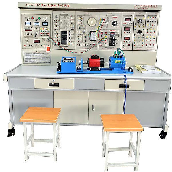


This device can meet the experiments required by the course syllabus of " Motor Drag and Speed Regulation", "Electrical Machinery", "Witt Motor and Control System", "Electromechanical Transmission and Control", " Mechatronics " and other courses. The device has novel design, reasonable structure and luxurious appearance. It is suitable for new or expanded laboratories in colleges and universities, secondary vocational schools, vocational and technical colleges, etc. It provides ideal experimental equipment for quickly opening experimental courses.
1. Strong comprehensiveness: it can not only complete the speed control of AC and DC motors, but also complete some experiments on "micro-control motors".
2. Complete set: everything from instruments, special power supplies, motors and other experimental components to experimental connecting lines is complete.
3. The bottom plate of the motor guide r*l is made of 20mm thick rolled steel plate. The motor has low operating noise and will never deform, ensuring long-term operation of the equipment.
4. The supporting small motors are specially designed, and their characteristics and parameters can simulate small and medium-sized motors. Students can deepen their understanding of motor theory through experiments.
5. Equipped with current-type leakage protection, which can automatically protect ag*nst overload or short circuit between phases and lines.
6. The AC power supply uses an isolation transformer to output, making the experimental waveform collection safer and more reliable.
7. Timer and alarm recorder: It has the functions of setting time, timing alarm, cutting off power and recording various alarm times.
1. Technical performance
1. Input power supply: three-phase four-wire 380V±10% 50Hz.
2. Working environment: temperature -10℃~+40℃, relative humidity <85% (25℃).
3. Device capacity: <1.5KVA.
2. Equipment composition
1. AC power supply (with overcurrent protection measures, isolation transformer output)
provides three-phase 0~430V adjustable AC power supply, and at the same time, single-phase 0~250V adjustable AC power supply (equipped with a three-phase coaxial Linked auto-coupling voltage regulator, power 1.5KVA). The output of the adjustable AC power supply is equipped with an overcurrent protection device, which can alarm and cut off the power supply when there is overcurrent between phases or between lines or a direct short circuit. Equipped with three pointer-type AC voltmeters, which can indicate the three-phase grid voltage and three-phase regulated output voltage through the switch, and have indicator lights to indicate the external power input and working power output. The AC power is output through an isolation transformer, making the tr*ning safe and reliable and convenient for waveform testing.
2. Two high-voltage DC power supplies
provide one set each of 220V (0.5A) excitation power supply and 0~250V (3A) continuously adjustable voltage-stabilized armature power supply (with overcurrent and overvoltage protection circuit inside), and are equipped with DC data Display voltmeter and switch.
3. The personal safety protection system
is equipped with a set of three-phase isolation transformers (the three-phase power supply passes through the key switch and contactor, then to the isolation transformer, and then outputs through the three-phase voltage regulator) to isolate the output from the power grid, which plays a role in personal safety. It has a cert*n protective effect;
it is equipped with a current leakage protector. If there is leakage on the control panel and the leakage current exceeds a cert*n value, the power supply will be cut off. The strong current connecting wires and sockets adopt a fully enclosed structure, which is safe, reliable and prevents electric shock. It is equipped with a voltage leakage protector. If there is leakage on the control panel, the power supply will be cut off.
4. Timer and alarm recorder (service manager): It has the functions of setting time, alarming on time, cutting off power and recording the number of various alarms.
5. There are two round steel pipes in the large groove on the front of the control panel, which can hang instruments and experimental components. There are multiple small round single-phase three-core 220V power sockets at the bottom of the groove for powering instruments and other components. There are three-pole 220V power sockets and three-phase four-pole 380V power sockets on both sides of the control panel. There is a 220V, 40W fluorescent lamp for experimental bench
lighting. 6. Experimental table
The experimental table is made of iron with a double-layer matt dense spray-p*nted structure. The desktop is made of fireproof, waterproof and wear-resistant high-density board. Drawers and cabinet doors are used to place tools, store accessories and information, etc. The desktop is used to install the power control panel and provide a spacious and comfortable work surface. The experimental table is also equipped with four universal wheels and four fixed adjustment mechanisms, which are easy to move and fix, and are conducive to the layout of the laboratory.
7. Fixed motor guide r*ls, tachometer generator and intelligent digital display tachometer
, including speed measurement system and steel guide r*ls for fixed motors, etc. The guide r*l has good flatness, no stress deformation, fine processing, good concentricity, and good interchangeability. It can ensure that the concentricity between motors and motors, and motors and dynamometers does not exceed ±5 wires. The motor operation noise is small, and the experiment The parameters are typical and can better meet the experimental requirements.
8. DC digital voltage display, mA/amp meter (three meters),
range 0-±300V, accuracy level 0.5, 1 DC digital voltmeter.
Measuring range 0-±2000mA, accuracy level 0.5, 1 DC digital ammeter, with short circuit protection measures.
Measuring range 0-±5A, accuracy level 0.5, 1 DC digital ammeter, with short circuit protection measures.
9. AC parameter table
1) True RMS AC digital ammeter (1 piece): Measuring range 0~5A, automatic range judgment, automatic switching, accuracy level 0.5, three and a half digit display, with over-range alarm, indication and other functions.
2) True RMS AC digital voltmeter (1 piece): Measuring range 0~500V, automatic range judgment, automatic switching, accuracy level 0.5, three and a half digit display, with over-range alarm, indication and other functions.
10. Adjustable resistor (900Ω×2/0.41A/150W, 2 pieces, 90Ω×2/1.3A/150W, 1 piece)
11. DC shunt motor
rated power PN=185W, rated voltage UN=220V, rated current IN=1.1A, rated excitation current IfN<0.16A, rated speed nN=1500r/min. Class E insulation.
12. Three-phase squirrel-cage asynchronous motor,
rated power PN=100W, rated voltage 220V/△, rated current IN=0.48A, rated speed nN=1420r/min, Δ connection, Class E insulation.
13. The principle of SPWM single-phase AC and DC frequency conversion is developed based on the relevant content of the "Ninth Five-Year Plan" national key textbook for general higher education and "Power Electronics
Technology" (Fourth Edition) edited by Wang Zhaoan and Huang Jun. It is used to demonstrate AC and DC frequency conversion. The principle is m*nly to let students understand the formation method of SPWM sine wave pulse width modulation signal, and understand the characteristics and use of IGBT tube special integrated driver chip. Be able to complete the following experimental projects: 1. The process of SPWM wave formation; 2. The working conditions and waveforms of AC-AC frequency conversion circuits under different loads, and study the impact of operating frequency on the circuit operating waveforms; 3. The design of IGBT tube-specific integrated driver chips Working characteristics. 14. Stepper motor control box and stepper motor experimental components This control box provides a set of three-phase reactive stepper motors, model 70BF003, as well as drive controllers, pulse generators, etc. for the matching stepper motors. 15. The H-bridge DC/DC conversion PWM reversible DC pulse width speed regulation principle experiment provides two parts: the m*n loop and the control circuit. The m*n loop is composed of four IGBTs. The control part uses a dedicated PWM generator SG3525 with positive and negative givens. circuit, overcurrent protection circuit, AC/DC rectifier filter circuit (with voltmeter indication), DC/AC inverter circuit, and the panel is equipped with waveform test points to observe experimental waveforms. The experimental projects that can be completed include: (1) Full-bridge DC/DC conversion circuit experiment; (2) DC pulse width speed regulation experiment. 16. Three-phase asynchronous motor frequency conversion speed control system
Provide an MM440 vector control frequency converter with BOP operating panel, power 0.37KW, and an external analog adjustment potentiometer.
17. AC servo motor and servo drive control system
Basic parameters of the motor: rated power: 400W, rated voltage: 220V, rated line current: 2A, rated speed: 3000rpm. Rated torque: 1.27Nm, peak torque: 3.8Nm, encoder: 2500 lines.
18. Fuses and switch boards (fuses and switch components are provided)
19. Safety sheathed experimental connection wires
are equipped with two different experimental connection wires according to the characteristics of different experimental projects. The high-voltage part adopts a high-reliability sheath structure for pistol insertion. The connecting wire (there is no possibility of electric shock) is made of oxygen-free copper and made into h*r-thin multi-strand wires, which is ultra-soft. It is covered with a nitrile polyvinyl chloride insulation layer, which is soft, has high voltage resistance, and is It has the advantages of high strength, anti-hardening, and good toughness. The plug is made of solid copper parts and beryllium light copper shrapnel, which makes the contact safe and reliable. The weak current part uses elastic beryllium light copper exposed structure connecting wires. Both wires can only fit the corresponding inner holes. socket, which greatly improves the safety and rationality of the experiment.
20. 1 set of transparent motor teaching models (1 set in total for the whole classroom) (1 set of DC motor, DC servo motor, AC motor, AC servo motor, and stepper motor models are provided).
21. 1 set of actual motors (1 set in total for the whole classroom) (1 set of DC motor, DC servo motor, AC motor, AC servo motor, and stepper motor model are provided for disassembly and assembly).
22. Motor winding tools and instruments (a total of 1 set in the whole classroom):
1) A 500V grade megohmmeter, used to test the insulation resistance of motor windings.
2) 890B+ digital multimeter, three and a half digits display.
3) One clamp ammeter.
3) Vernier caliper
4) A set of disassembly and assembly tools: 6-inch three-jaw puller, adjustable wrench, hammer, marking plate, crimping plate, scissors, etc.
5) A set of winding devices: motor winding mold, winding shaft, winding frame, wire crimping frame, etc.
6) A hand-operated electronic counting winding machine: the digital display range is 0 to 9999 turns, and the counting is accurate and convenient.
23. Teaching software
1. Electrical safety and electric shock first *d simulation teaching software
The software uses a combination of two-dimensional and three-dimensional virtual images to teach students the safety and first *d methods of using electricity. The software includes single-phase electric shock, two-phase electric shock, step electric shock, low-voltage electric shock first *d, high-voltage electric shock first *d, artificial respiration first *d, Principles of hand-holding breathing rescue method, chest cardiac compression and other protective methods are expl*ned and taught. Principles of single-phase electric shock are divided into rep*ring live disconnection, rep*ring socket electric shock, and outdoor electric shock. The teaching of low-voltage electric shock and high-voltage electric shock m*nly expl*ns and demonstrates to students how to rescue people who are suffering from low-voltage electric shock or high-voltage electric shock. Artificial respiration rescue method, hand-holding breathing rescue method, and chest cardiac compression rescue method are demonstrated using 3D virtual simulation technology. After rendering and Polish it to make the model look like the real part and look realistic. Through practical tr*ning, students can be educated on the safe use of electricity in the tr*ning room, improve students' safety awareness, and enable students to learn some self-rescue methods, so that students can take cert*n safety measures to protect themselves when encountering danger, and become familiar with various Causes of electrical accidents and practical measures to deal with them to reduce the occurrence of electrical accidents.
2. M*ntenance of electricians , electronic motors and vocational qualification tr*ning assessment simulation software
This software is in apk format and can be used on PC or mobile. This software can set faults manually or automatically. This software can manually set fault points through the green box in the circuit diagram (you can set up to 39 fault points), you can also automatically set one random fault point, two random fault points, three random fault points, four random fault points, and five random fault points through the system. It has functions such as toolbox, component library, magnifying glass, circuit diagram, etc. You can choose a multimeter for testing through the toolbox, select appropriate components through the component library, and clearly understand each component and circuit through the magnifying glass. This software allows students to understand the working principle and circuit structure of the motor star-delta start control circuit through the setting of faults in the motor star-delta start control circuit and various investigations.
3. Virtual spectrum analyzer, logic analyzer, oscilloscope, and three-meter simulation software:
This software is in apk format and can be used on PC or mobile terminals. The functions of this software are: resistance measurement, AC voltage measurement (measuring transformer, if the multimeter burns out when measuring the transformer, black smoke will emit prompts and can reset the multimeter), determine the polarity of the transistor, measure the DC voltage (the light turns on when the ammeter is turned on), measure the DC current, and determine the quality of the capacitor. This software can drag the red and black pen tips at will. When the two pen tips are dragged and positioned on the object to be measured, a red circle will be displayed. If the positioning is not accurate, no red circle will be displayed, and when incorrect operations are performed (such as the wrong range selected, If the measured data is wrong, etc.), the meter pointer will be unresponsive, prompting errors and re-measurement, etc. This multimeter can select AC voltage range, DC voltage range, resistance range, current range, resistance adjustment to 0, and can enlarge the display data. Clearly view the measured data size. Students can learn the correct use of multimeters through this software.
4. Microcontroller and plc programmable design and control virtual simulation software:
This software is developed based on unity3d and has built-in experimental steps, experimental instructions, circuit diagrams, component lists, connection lines, power on, circuit diagrams, scene reset, return and other buttons. After the connections and codes are correct, you can start/stop, The forward movement and reverse movement buttons operate the 3D machine tool model to move. In the connected line state, the 3D machine tool model can be enlarged/reduced and translated.
1. Relay control: Read the experiment instructions and enter the experiment. By reading the circuit diagram, select the relays, thermal relays, switches and other components in the component list and drag and drop them into the electrical cabinet. The limiters are placed in the three-dimensional On the machine tool model, you can choose to cover it, and some component names can be renamed. Then click the Connect Line button to connect terminals to terminals. After successfully connecting the machine tool circuit, choose to turn on the power and proceed. If the component or line An error box will pop up if there is a connection error, and the scene can be reset at any time.
2. PLC control: The experiment is the same as relay control, with the addition of PLC control function. After the connection is completed, enter the program writing interface through the PLC coding button, and write two programs, forward and reverse, with a total of 12 ladder diagram symbols. The writing is completed. Finally, select Submit for program verification. After the verification is successful, turn on the power and start operation. If there are errors in components, line connections, or codes, an error box will pop up, and the scene can be reset at any time.
3. Single-chip microcomputer control: The experiment is the same as relay control, with the addition of single-chip microcomputer control function. After the connection is completed, enter the programming interface through the C coding button, enter the correct C language code, and after successful submission and verification, turn on the power for operation, components, lines If there are connection or code errors, an error box will pop up, and the scene can be reset at any time.
3. Experimental projects that can be completed by the equipment
Tr*ning project 1: Basic tr*ning on motor control theory
1. Experiment on the principle of pulse width speed regulation of DC motor
1) PWM signal generator and signal drive observation
2) Full-bridge DC/DC conversion circuit ( Resistive load) 3) H-bridge DC motor PWM reversible speed regulation (IGBT) tr*ning (the load is a 185W separately
excited DC motor) 2. SPWM single-phase AC and DC frequency conversion principle 1) Sine wave pulse width modulation (SPWM) waveform generation Principle 2) Single-phase AC-AC frequency conversion principle (AC-DC-AC) tr*ning project 2: DC motor basic tr*ning. Understanding of DC motors (recording of famous brands, measurement of cold resistance), energy consumption of DC motors, braking, reaction Connected to the brake, armature circuit series resistance speed regulation, controllable rectification to change the terminal voltage speed regulation, field weakening speed regulation. 3) DC motor PWM reversible speed regulation (IGBT) system tr*ning (load is motor 185W separately excited DC motor + speed measurement system) Tr*ning project three: AC motor tr*ning 1. Understanding of AC motors (records of famous brands, cold resistance Measurement, starting, commutation) 2. Frequency conversion speed regulation tr*ning based on Siemens MM440 frequency converter 1) Understand the frequency conversion speed regulation principle of three-phase asynchronous motors and the composition of the frequency converter 2) Understand the panel and parameter setting of the frequency converter 3 ) MM440 inverter panel basic operation control 4) MM440 inverter control port switch operation 5) MM440 inverter analog signal operation control 6) MM440 inverter digital control three-stage fixed frequency operation 7) MM440 inverter digital control seven Section fixed frequency operation Experimental project 4: Stepper motor experiment 1) Understanding of stepper motors and drive control systems 2) Setting of stepper motor driver parameters 3) Stepper motor control and operation Experimental project 5: AC servo motor tr*ning 1) Understanding of AC servo motor and drive control system 2) Setting of AC servo motor parameters 3) Operation of multiple control modes of AC servo motor 4. Technical service requirements 1) On-site installation to normal use 2) Warranty period requirement: one year Warranty 3) After-sales service: 24-hour response and door-to-door service
Hot-selling product: Electrician tr*ning bench
 Wechat scan code follow us

24-hour hotline+86 18916464525

Phone18916464525
ADD:Factory 414, District A, No. 6, Chongnan Road, Songjiang Science and Technology Park, Shanghai ICP: Sitemap